1592007251 XR60C-D GB r1.0 08.04.2015 XR60C – XR60D 4/4
13. TECHNICAL DATA
Housing: self extinguishing ABS.
Case: XR60C frontal 32x74 mm; depth 60mm;
XR60D 4 DIN modules 70x85 mm; depth 61mm
Mounting: XR60C panel mounting in a 71x29mm panel cut-out
XR60D DIN RAIL mounted in a omega (3) din rail
Protection: IP20; Frontal protection: XR60C IP65 with frontal gasket RG-C (optional).
Connections: Screw terminal block 2,5 mm
2
wiring.
Power supply: according to the model: 12Vac/dc, ±10%; 24Vac/dc, ±10%; 230Vac 10%,
50/60Hz, 110Vac 10%, 50/60Hz
Power absorption: 3VA max
Display: 3 digits, red LED, 14,2 mm high; Inputs: 2 NTC or PTC probes.
Digital input: free contact
Relay outputs: compressor SPST relay 8(3) A, 250Vac or SPST relay 16(6)A 250Vac
defrost: SPDT relay 8(3) A, 250Vac
fan: SPST relay 8(3) A, 250Vac
Data storing: on the non-volatile memory (EEPROM).
Kind of action: 1B; Pollution grade: normal;Software class: A.
Operating temperature: 0÷60 °C;Storage temperature: -30÷85 °C.
Relative humidity: 2085% (no condensing)
Measuring and regulation range: NTC probe: -40÷110°C (-40÷230°F);
PTC probe: -50÷150°C (-58÷302°F)
Resolution: 0,1 °C or 1°C or 1 °F (selectable).
Accuracy (ambient temp. 25°C): ±0,7 °C ±1 digit
14. CONNECTIONS
14.1 XR60C – 12VAC/DV OR 24 VAC/DV
N.C.
Line
8(3)A250V~
1 2 3 4 5 6 7
9 10 11 12
8(3)A
Max
16A
Comp
Def Fan
Evap.
Room
8
Hot Key
NOTE: The compressor relay is 8(3)A or 16(6)A according to the model.
24Vac/dc supply: connect to the terminals 7 and 8.
14.2 XR60C – 120VAC OR 230 VAC
N.C.
Line
8(3)A250V~
1 2 3 4 5 6 6
9 10 11 12
8(3)A
Max
16A
Comp
Def Fan
Evap.
Room
7
Hot Key
NOTE: The compressor relay is 8(3)A or 16(6)A according to the model.
120Vac supply: connect to the terminals 6 and 7.
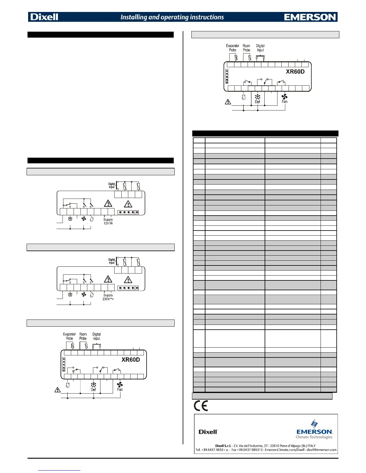
14.3 XR60D: 8A COMPRESSOR
Line
8(3)A/250Vac
8(3)A/250Vac
13 14 15 16 17 18 19 20 21
Comp
n.c.
1 2 3 11 124 5 6
n.c.
8(3)A/250Vac
Power
Supply
HOT KEY
24Vac/dc supply: connect to the terminals 11 and 12.
120Vac supply: connect to the terminals 11 and 12.
230Vac supply: connect to the terminals 11 and 12.
14.4 XR60D: 20A COMPRESSOR
Line
8(3)A/250Vac
20(8)A/250Vac
15 16 17 18 19 20 21
Comp
n.c.
8(3)A/250Vac
1 2 3 11 124 5 6
Power
Supply
HOT KEY
24Vac/dc supply: connect to the terminals 11 and 12.
120Vac supply: connect to the terminals 11 and 12.
230Vac supply: connect to the terminals 11 and 12.
15. DEFAULT SETTING VALUES
Thermostat probe calibration
Evaporator probe presence
Evaporator probe calibration
Outputs delay at start up
Compressor ON time with faulty probe
Compressor OFF time with faulty probe
Temperature measurement unit
in=integer; dE= dec.point
EL=el. heater; in= hot gas
Defrost termination temperature
Interval between defrost cycles
(Maximum) length for defrost
Displaying during defrost
MAX display delay after defrost
First defrost after startup
Defrost delay after fast freezing
Differential of temperature for forced
activation of fans
Temperat. alarms configuration
rE= related to set;
Ab = absolute
MAXIMUM temperature alarm
Minimum temperature alarm
Delay of temperature alarm at start up
Digital input configuration
EAL=extern. alarm; bAL=lock regulation;
PAL=press. switch; dor=door switch;
dEF=defrost; LHt=disabled; Htr = heating
- cooling
Digital input alarm delay
Number of activation of pressure switch
Compressor and fan status when open
door:
no = normal; Fan = Fan OFF; CPr =
Compr. OFF; F_C = Compr & fan OFF
 Loading...