EasyManua.ls Logo

Emerson dixell XR60CX - User Manual

Emerson dixell XR60CX
4 pages
Print Icon
To Next Page IconTo Next Page
Loading...
1592020060 XR60CX GB m&M r1.1 29.08.2013.doc XR60C 1/4
Digital controller with defrost and fans management
XR60CX
CONTENTS
1.
GENERAL WARNING __________________________________________________________ 1
2.
GENERAL DESCRIPTION ______________________________________________________ 1
3.
CONTROLLING LOADS ________________________________________________________ 1
4.
FRONT PANEL COMMANDS ____________________________________________________ 1
5.
MAX & MIN TEMPERATURE MEMORIZATION _____________________________________ 1
6.
MAIN FUNCTIONS ____________________________________________________________ 2
7.
PARAMETERS _______________________________________________________________ 2
8.
DIGITAL INPUT (ENABLED WITH P3P = N) ________________________________________ 3
9.
TTL SERIAL LINE – FOR MONITORING SYSTEMS _________________________________ 3
10.
X-REP OUTPUT – OPTIONAL ___________________________________________________ 3
11.
INSTALLATION AND MOUNTING ________________________________________________ 3
12.
ELECTRICAL CONNECTIONS___________________________________________________ 3
13.
HOW TO USE THE HOT KEY ___________________________________________________ 3
14.
ALARM SIGNALS _____________________________________________________________ 3
15.
TECHNICAL DATA ____________________________________________________________ 4
16.
CONNECTIONS ______________________________________________________________ 4
17.
DEFAULT SETTING VALUES ___________________________________________________ 4
1. GENERAL WARNING
1.1 PLEASE READ BEFORE USING THIS MANUAL
This manual is part of the product and should be kept near the instrument for easy and quick
reference.
The instrument shall not be used for purposes different from those described hereunder. It
cannot be used as a safety device.
Check the application limits before proceeding.
Dixell Srl reserves the right to change the composition of its products, even without notice,
ensuring the same and unchanged functionality.
1.2
SAFETY PRECAUTIONS
Check the supply voltage is correct before connecting the instrument.
Do not expose to water or moisture: use the controller only within the operating limits avoiding
sudden temperature changes with high atmospheric humidity to prevent formation of
condensation
Warning: disconnect all electrical connections before any kind of maintenance.
Fit the probe where it is not accessible by the End User. The instrument must not be opened.
In case of failure or faulty operation send the instrument back to the distributor or to “Dixell
S.p.A.” (see address) with a detailed description of the fault.
Consider the maximum current which can be applied to each relay (see Technical Data).
Ensure that the wires for probes, loads and the power supply are separated and far enough from
each other, without crossing or intertwining.
In case of applications in industrial environments, the use of mains filters (our mod. FT1) in
parallel with inductive loads could be useful.
2. GENERAL DESCRIPTION
Model XR60CX, format 32 x 74 mm, is microprocessor based controller, suitable for applications on
medium or low temperature ventilated refrigerating units. It has three relay outputs to control
compressor, fan, and defrost, which can be either electrical or reverse cycle (hot gas). It is also
provided with three NTC or PTC probe inputs, the first one for temperature control, the second one, to
be located onto the evaporator, to control the defrost termination temperature and to managed the fan,
the third one, optional, to connect to the HOT KEY terminals to signal the condenser temperature
alarm or to display a temperature. The digital input can operate as fourth temperature probe.
The HOT KEY output allows to connect the unit, by means of the external module XJ485-CX, to a
network line ModBUS-RTU compatible such as the dIXEL monitoring units of X-WEB family. It
allows to program the controller by means the HOT KEY programming keyboard.
The instrument is fully configurable through special parameters that can be easily programmed
through the keyboard.
3. CONTROLLING LOADS
3.1 COMPRESSOR
The regulation is performed according to
the temperature measured by the
thermostat probe with a positive
differential from the set point: if the
temperature increases and reaches set
point plus differential the compressor is
started and then turned off when the
temperature reaches the set point value
again.
Time
Temper.
Compr.
SET
ON
In case of fault in the thermostat probe the start and stop of the compressor are timed through
parameters “COn” and “COF”.
3.2 DEFROST
Two defrost modes are available through the “tdF” parameter: defrost through electrical heater (tdF =
EL) and hot gas defrost (tdF = in). Other parameters are used to control the interval between defrost
cycles (IdF), its maximum length (MdF) and two defrost modes: timed or controlled by the evaporator’s
probe (P2P).
At the end of defrost dripping time is started, its length is set in the FSt parameter. With FSt =0 the
dripping time is disabled.
3.3 CONTROL OF EVAPORATOR FANS
The fan control mode is selected by means of the FnCparameter:
FnC = C_n: fans will switch ON and OFF with the compressor and not run during defrost;
FnC = o_n fans will run even if the compressor is off, and not run during defrost;
After defrost, there is a timed fan delay allowing for drip time, set by means of the Fnd” parameter.
FnC = C_Y fans will switch ON and OFF with the compressor and run during defrost;
FnC = o_Y fans will run continuously also during defrost
An additional parameter FStprovides the setting of temperature, detected by the evaporator probe,
above which the fans are always OFF. This is used to make sure circulation of air only if his
temperature is lower than set in “FSt”.
3.3.1 Forced activation of fans
This function managed by the Fct parameter is designed to avoid short cycles of fans, that could
happen when the controller is switched on or after a defrost, when the room air warms the evaporator.
Functioning: if the difference of temperature between the evaporator and the room probes is more
than the value of the Fct parameter, the fans are switched on. With Fct=0 the function is disabled.
3.3.2 Cyclical activation of the fans with compressor off.
When Fnc = c-n or c-Y (fans in parallel to the compressor), by means of the Fon and FoF parameters
the fans can carry out on and off cycles even if the compressor is switched off. When the compressor
is stopped the fans go on working for the Fon time. With Fon =0 the fans remain always off, when the
compressor is off.
4. FRONT PANEL COMMANDS
: To display target set point; in programming mode it selects a parameter or confirm an
operation.
(DEF) To start a manual defrost
(UP): To see the max. stored temperature; in programming mode it browses the parameter
codes or increases the displayed value.
(DOWN) To see the min stored temperature; in programming mode it browses the parameter
codes or decreases the displayed value.
To switch the instrument off, if onF = oFF.
Not enabled.
KEY COMBINATIONS:
+
To lock & unlock the keyboard.
+
To enter in programming mode.
+
To return to the room temperature display.
4.1 USE OF LEDS
Each LED function is described in the following table.
LED MODE FUNCTION
ON Compressor enabled
Flashing Anti-short cycle delay enabled
ON Defrost enabled
Flashing Drip time in progress
ON Fans enabled
Flashing Fans delay after defrost in progress.
ON An alarm is occurring
ON Continuous cycle is running
ON Energy saving enabled
°C/°F
ON Measurement unit
°C/°F
Flashing Programming phase
5. MAX & MIN TEMPERATURE MEMORIZATION
5.1 HOW TO SEE THE MIN TEMPERATURE
1.
Press and release the n
nn
n key.
2.
The “Lo” message will be displayed followed by the minimum temperature recorded.
3.
By pressing the n
nn
n key again or by waiting 5s the normal display will be restored.
5.2 HOW TO SEE THE MAX TEMPERATURE
1.
Press and release the o
oo
o key.
2.
The “Hi” message will be displayed followed by the maximum temperature recorded.
3.
By pressing the o
oo
o key again or by waiting 5s the normal display will be restored.
5.3 HOW TO RESET THE MAX AND MIN TEMPERATURE RECORDED
1. Hold press the SET key for more than 3s, while the max. or min temperature is displayed. (rSt
message will be displayed)
Question and Answer IconNeed help?

Do you have a question about the Emerson dixell XR60CX and is the answer not in the manual?

Summary

General Warnings and Safety Precautions

Read Before Using This Manual

Essential guidance for users to read the manual before operating the instrument.

Safety Precautions

Crucial safety measures to follow during installation and operation of the controller.

General Description of XR60 CX Controller

Controlling Loads: Compressor, Defrost, and Fans

Compressor Control

Details on how the compressor is regulated based on temperature setpoints and differentials.

Defrost Functions

Explanation of available defrost modes, intervals, and termination methods.

Evaporator Fan Control

Configuration options for evaporator fan operation modes, including timed and continuous cycles.

Front Panel Commands and Indicators

LED Functions

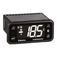
Description of each LED indicator and its corresponding function during operation.

Temperature Memorization Features

Viewing Minimum Temperature

Instructions on how to display the lowest recorded temperature.

Viewing Maximum Temperature

Instructions on how to display the highest recorded temperature.

Resetting Max;Min Temperatures

Procedure to reset the stored maximum and minimum temperature values.

Main Functions and Operations

Viewing and Changing Setpoint

How to display and modify the target temperature setpoint.

Starting Manual Defrost

Procedure for manually initiating a defrost cycle.

Parameter Value Adjustment

Steps for changing parameter values in the standard and hidden menus.

Locking and Unlocking Keyboard

How to enable or disable the front panel keyboard to prevent accidental changes.

Continuous Cycle Operation

Description of the continuous cycle feature for compressor operation.

On;Off Functionality

How to switch the instrument on and off using the dedicated key.

Parameter Reference Guide

Regulation Parameters

Parameters related to temperature regulation, setpoints, and differentials.

Display Parameters

Settings for display units, resolution, and probe visualization.

Defrost Parameters

Configuration options for defrost type, termination, intervals, and delays.

Fan Parameters

Settings controlling evaporator fan operation modes and timing.

Alarm Parameters

Configuration for temperature alarms, differentials, and delays.

Digital Inputs and Alarms

Digital Input Configuration

Settings for digital input polarity and functional configuration (door, alarm, defrost).

Alarm Recovery and Messages

How alarms recover and the meaning of various alarm messages displayed.

Other Messages

Meaning of additional status messages like 'Pon' and 'POF'.

Advanced Features and Connectivity

Serial Line for Monitoring

Connecting the controller to monitoring systems via TTL serial line.

X-REP Output Option

Information on connecting an optional X-REP module.

Hot Key Usage

Instructions for programming and using the Hot Key for data upload/download.

Installation and Electrical Connections

Installation and Mounting

Guidelines for panel mounting the XR60CX controller and environmental considerations.

Probe Connection

Recommendations for correctly connecting temperature probes.

Electrical Connections

Details on wiring the controller, including power supply and output connections.

Alarm Signals and Recovery

Alarm Signals

Table listing alarm messages, their causes, and output status.

Alarm Recovery

How various alarm conditions are recovered and reset.

Technical Data and Default Settings

Technical Data

Specifications for housing, dimensions, power, inputs, outputs, and operating ranges.

Default Setting Values

Table of default parameter values for quick configuration.

Connections Diagrams

Wiring diagrams for different XR60CX models and power supply options.

Overview

The Dixell XR60CX is a microprocessor-based digital controller designed for medium and low-temperature ventilated refrigerating units. This device offers comprehensive control over various aspects of a refrigeration system, including compressor, fan, and defrost management. Its compact format (32 x 74 mm) and user-friendly interface make it suitable for a wide range of applications.

Function Description

The XR60CX features three relay outputs to control the compressor, fan, and defrost functions. Defrost can be configured for either electrical heater or hot gas operation. The controller is equipped with three NTC or PTC probe inputs. The first probe is dedicated to temperature control, ensuring precise regulation of the refrigerated environment. The second probe is strategically placed on the evaporator to manage defrost termination temperature and fan operation. An optional third probe can be connected to the HOT KEY terminals to signal condenser temperature alarms or display an additional temperature reading. Furthermore, a digital input can function as a fourth temperature probe, enhancing monitoring capabilities.

The regulation of the compressor is based on the temperature measured by the thermostat probe. The compressor starts when the temperature reaches the set point plus a positive differential (Hy) and turns off when the temperature returns to the set point. In the event of a thermostat probe failure, the compressor's start and stop times are managed by the "COn" and "COF" parameters, ensuring continued operation.

Defrost management offers two modes: electrical heater (tdF = EL) or hot gas (tdF = in). Parameters like "IdF" (interval between defrost cycles) and "MdF" (maximum defrost length) allow for flexible scheduling. Defrost can be timed or controlled by the evaporator probe (P2P). After defrost, a dripping time ("FSt" parameter) is initiated to allow water to drain, with the option to disable it.

The XR60CX provides extensive control over evaporator fans. The "FnC" parameter defines the fan operating mode: fans can switch ON and OFF with the compressor (C_n, C_Y) or run continuously (o_n, o_Y). During defrost, fans can be configured to be OFF (C_n, o_n) or ON (C_Y, o_Y). A timed fan delay ("Fnd") after defrost allows for drip time. The "FSt" parameter sets a temperature threshold, above which fans are always OFF, ensuring air circulation only when the temperature is below this value. To prevent short cycling, a forced activation of fans can be enabled via the "Fct" parameter, switching fans on if the temperature difference between evaporator and room probes exceeds a set value. Cyclical activation of fans with the compressor off is also possible using "Fon" and "FoF" parameters, allowing fans to run in cycles even when the compressor is inactive.

The controller includes a continuous cycle function, activated by holding the UP key for 3 seconds. During this cycle, the compressor operates continuously for a time set by "CCt" to maintain a specific set point ("CCS"), useful for rapid cooling of new products. This cycle can be manually terminated. An ON/OFF function, controlled by the "onF" parameter, allows the instrument to be switched off, disabling regulation and displaying "OFF."

Alarm management is comprehensive, covering temperature alarms (ALU, ALL), condenser temperature alarms (AL2, AU2), and digital input alarms. Temperature alarms can be configured as absolute (Ab) or relative (rE) to the set point. Delays ("ALd," "dAO," "Ad2," "dA2") are incorporated to prevent nuisance alarms. The controller can also manage compressor shutdown based on low or high condenser temperature alarms ("bLL," "AC2").

The digital input is highly versatile and programmable via the "i1F" parameter. It can be configured as a door switch ("dor"), generic alarm ("EAL"), serious alarm ("bAL"), pressure switch ("PAL"), defrost activation ("dFr"), action inversion (cooling/heating, "Htr"), or energy saving ("ES"). Each configuration triggers specific responses from the controller, such as displaying messages, controlling outputs, or modifying the set point.

Usage Features

The front panel features intuitive commands for easy operation. The "SET" key allows users to display and modify the target set point. A manual defrost can be initiated by holding the "DEF" key. The "UP" and "DOWN" keys are used to view stored maximum and minimum temperatures, browse parameter codes, and adjust displayed values. A key combination (SET + UP) locks and unlocks the keyboard, preventing accidental changes. Another combination (SET + DOWN) provides access to the programming mode.

The controller offers two levels of parameter access: a "First Level" (user level) and a "Hidden Menu" containing all parameters. Parameters can be moved between these levels for customized access. The display provides clear indications of operational status through various LEDs, signaling compressor activity, defrost in progress, fan operation, alarms, continuous cycle, energy saving, and programming phase.

The HOT KEY output enables easy programming of the controller using a dedicated keyboard. It also allows connection to a ModBUS-RTU compatible monitoring system, such as Dixell's X-WEB family, via an external XJ485-CX module. This facilitates remote monitoring and management of the refrigeration unit. The HOT KEY can also be used to upload settings from one controller to another or download pre-programmed settings, simplifying installation and configuration for multiple units.

Maintenance Features

For maintenance, the manual emphasizes safety precautions, including disconnecting all electrical connections before any work. The instrument is designed for durability, with a self-extinguishing ABS housing and IP65 frontal protection. The non-volatile memory (EEPROM) ensures that stored data and settings are retained even during power outages.

The device includes self-diagnostic capabilities, indicated by alarm messages such as "P1," "P2," "P3," and "P4" for probe failures. These alarms automatically clear once the probe returns to normal operation or the fault is resolved. Temperature alarms ("HA," "LA," "HA2," "LA2") also reset automatically when temperatures return to normal. Digital input alarms ("EA," "CA") recover when the input is disabled or the instrument is reset.

The manual provides detailed instructions for electrical connections, emphasizing the separation of probe cables from power supply and load cables to prevent interference. It also advises on proper probe placement to ensure accurate temperature measurements and effective defrost termination. The use of mains filters (e.g., Dixell FT1) is recommended in industrial environments to mitigate the effects of inductive loads.

Emerson dixell XR60CX Specifications

General IconGeneral
ModelXR60CX
Output TypeRelay
Digital Inputs2
Front Panel ProtectionIP65
Protection RatingIP65
TypeController
Input TypeNTC
Power Supply230 V AC
Measuring RangeDepends on the probe used
Resolution0.1 °C
Accuracy±0.5 °C
Serial OutputRS485
DisplayLCD
CommunicationModbus RTU

Related product manuals