1592020060 XR60CX GB m&M r1.1 29.08.2013.doc XR60C 4/4
Message Cause Outputs
“dA” Door open Compressor and fans restarts
“EA” External alarm Output unchanged.
“CA” Serious external alarm (i1F=bAL) All outputs OFF.
“CA” Pressure switch alarm (i1F=PAL) All outputs OFF
14.1 ALARM RECOVERY
Probe alarms P1”, “P2”, “P3” and “P4” start some seconds after the fault in the related probe; they
automatically stop some seconds after the probe restarts normal operation. Check connections before
replacing the probe.
Temperature alarms “HA”, “LA” “HA2” and “LA2” automatically stop as soon as the temperature
returns to normal values.
Alarms “EA” and “CA” (with i1F=bAL) recover as soon as the digital input is disabled.
Alarm “CA” (with i1F=PAL) recovers only by switching off and on the instrument.
14.2 OTHER MESSAGES
Pon
Keyboard unlocked.
PoF
Keyboard locked
noP
In programming mode: none parameter is present in Pr1
On the display or in dP2, dP3, dP4: the selected probe is nor enabled
noA None alarm is recorded.
15. TECHNICAL DATA
Housing: self extinguishing ABS.
Case: XR60CX frontal 32x74 mm; depth 60mm;
Mounting: XR60CX panel mounting in a 71x29mm panel cut-out
Protection: IP20; Frontal protection: XR60CX IP65
Connections: Screw terminal block ≤ 2,5 mm
2
wiring.
Power supply: according to the model: 12Vac/dc, ±10%; 24Vac/dc, ±10%; 230Vac ±10%, 50/60Hz,
110Vac ±10%, 50/60Hz
Power absorption: 3VA max
Display: 3 digits, red LED, 14,2 mm high; Inputs: Up to 4 NTC or PTC probes.
Digital input: free voltage contact
Relay outputs: compressor SPST 8(3) A, 250Vac; SPST 16(6)A 250Vac or 20(8)A 250Vac
defrost: SPDT 8(3) A, 250Vac
fan: SPST 8(3) A, 250Vac or SPST 5(2) A
Data storing: on the non-volatile memory (EEPROM).
Kind of action: 1B; Pollution grade: 2;Software class: A.;
Rated impulsive voltage: 2500V; Overvoltage Category: II
Operating temperature: 0÷60 °C;Storage temperature: -30÷85 °C.
Relative humidity: 20÷85% (no condensing)
Measuring and regulation range: NTC probe: -40÷110°C (-40÷230°F);
PTC probe: -50÷150°C (-58÷302°F)
Resolution: 0,1 °C or 1°C or 1 °F (selectable); Accuracy (ambient temp. 25°C): ±0,7 °C ±1 digit
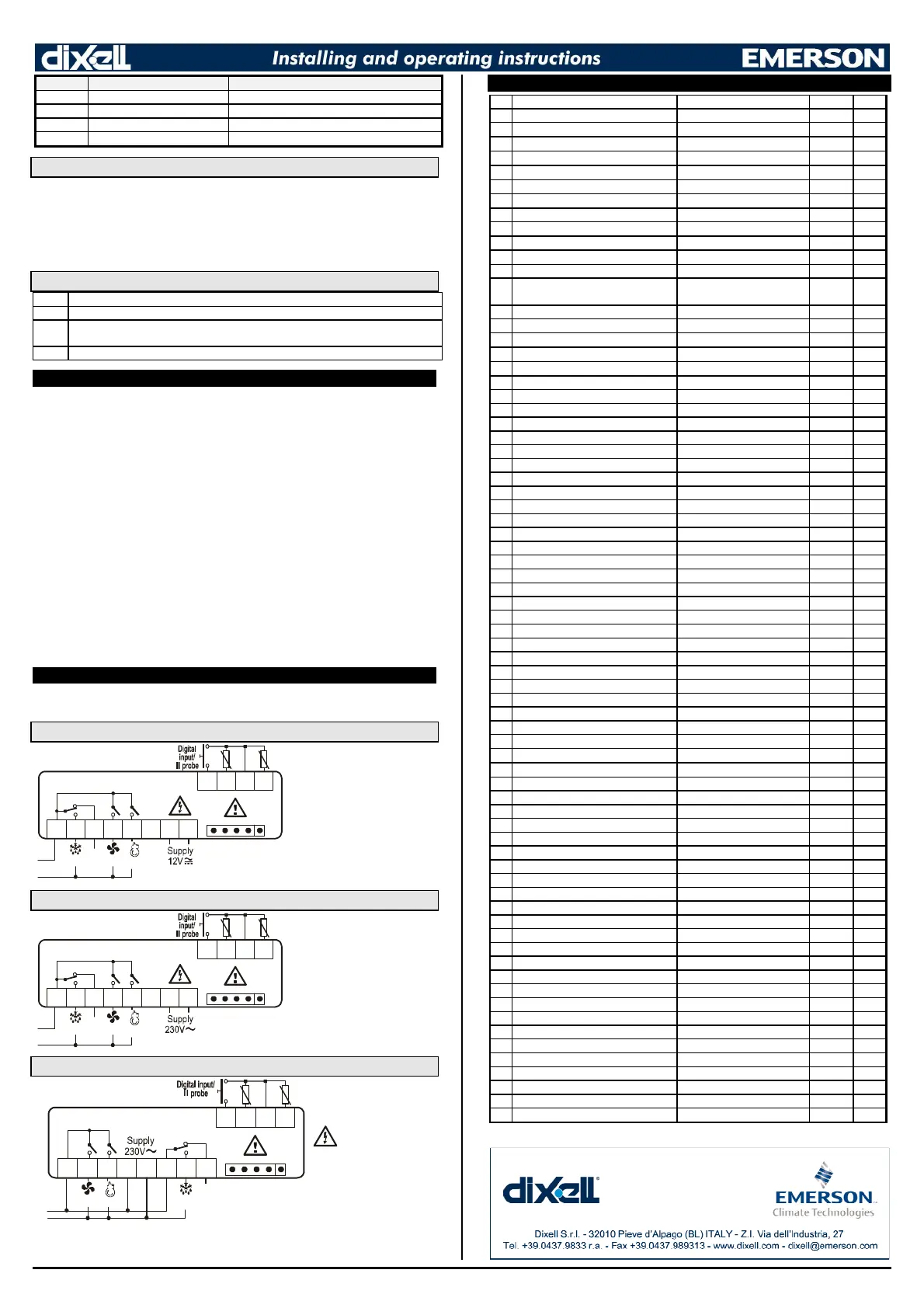
16. CONNECTIONS
The X-REP output excludes the TTL output.. It’s present in the following codes:
XR60CX- xx2xx, XR60CX –xx3xx;
16.1 XR60CX – 8A OR 16A COMP. RELAY - 12VAC/DV OR 24 VAC/DV
N.C.
Line
8(3)A250V
~
1
11
1 2
22
2 3
33
3 4
44
4 5
55
5
10
1010
10 11
1111
11
8(3)A
Max
16A
Comp
Def Fan
Evap.
Room
NOTE:
The compressor relay is
8(3)A or 16(6)A according to the
model.
24Vac/dc supply
: connect to the
terminals 7 and 8.
16.2 XR60CX – 8A OR 16A COMP. RELAY - 120VAC OR 230 VAC
N.C.
Line
8(3)A250V
~
1
11
1 2
22
2 3
33
3 4
44
4 5
55
5
10
1010
10 11
1111
11
8(3)A
Max
16A
Comp
Def Fan
Evap.
Room
NOTE:
The compressor relay is
8(3)A or 16(6)A according to the
model.
120Vac supply
: connect to the
terminals 6 and 7.
16.3 XR60C – 20A COMP. RELAY - 120VAC OR 230 VAC
N.C.
Line
8(3)A250V
~
1
11
1 2
22
2 3
33
3 4
44
4 5
55
5 6
66
66
66
6
10
1010
10 11
1111
11 12
1212
12
5(1)A
Max
20A
Comp
Def
Fan
8
88
8
20(8)A250V
~
120Vac supply
:
connect to the
terminals 5 and 6.
17. DEFAULT SETTING VALUES
Name Range °C/°F
Set
Set point LS÷US -5.0 - - -
Hy
Differential
0,1
÷
25.5°C/ 1
÷
255°F
2.0 Pr1
LS
Minimum set point
-50°C
÷
SET/-58°F
÷
SET
-50.0 Pr2
US
Maximum set point
SET
÷
110°C/ SET
÷
230°F
110 Pr2
Ot
Thermostat probe calibration
-12
÷
12°C /-120
÷
120°F
0.0 Pr1
P2P
Evaporator probe presence n=not present; Y=pres. Y Pr1
OE
Evaporator probe calibration
-12
÷
12°C /-120
÷
120°F
0.0 Pr2
P3P
Third probe presence n=not present; Y=pres. n Pr2
O3
Third probe calibration
-12
÷
12°C /-120
÷
120°F
0 Pr2
P4P
Fourth probe presence n=not present; Y=pres. n Pr2
O4
Fourth probe calibration
-12
÷
12°C /-120
÷
120°F
0 Pr2
OdS
Outputs delay at start up 0÷255 min 0 Pr2
AC
Anti-short cycle delay
0
÷
50 min
1 Pr1
rtr
P1-P2 percentage for regulation 0 ÷ 100 (100=P1 , 0=P2) 100 Pr2
CCt
Continuos cycle duration 0.0÷24.0h 0.0 Pr2
CCS
Set point for continuous cycle (-55.0÷150,0°C) (-67÷302°F) -5 Pr2
COn
Compressor ON time with faulty probe
0
÷
255 min
15 Pr2
COF
Compressor OFF time with faulty probe
0
÷
255 min
30 Pr2
CF
Temperature measurement unit
°C
÷
°F
°C Pr2
rES
Resolution
in=integer; dE= dec.point
dE Pr1
Lod
Probe displayed
P1;P2
P1 Pr2
rEd
2
X-REP display P1 - P2 - P3 - P4 - SEt - dtr P1 Pr2
dLy
Display temperature delay 0 ÷ 20.0 min (10 sec.) 0 Pr2
dtr
P1-P2 percentage for disply 1 ÷ 99 50 Pr2
tdF
Defrost type
EL=el. heater; in= hot gas
EL Pr1
dFP
Probe selection for defrost termination nP; P1; P2; P3; P4 P2 Pr2
dtE
Defrost termination temperature
-50 ÷ 50 °C
8 Pr1
IdF
Interval between defrost cycles
1 ÷ 120 ore
6 Pr1
MdF
(Maximum) length for defrost
0 ÷ 255 min
30 Pr1
dSd
Start defrost delay
0÷99min
0 Pr2
dFd
Displaying during defrost
rt, it, SEt, DEF
it Pr2
dAd
MAX display delay after defrost 0 ÷ 255 min 30 Pr2
Fdt
Draining time 0÷120 min 0 Pr2
dPo
First defrost after startup n=after IdF; y=immed. n Pr2
dAF
Defrost delay after fast freezing 0 ÷ 23h e 50’ 0.0 Pr2
Fnc
Fan operating mode C-n, o-n, C-y, o-Y o-n Pr1
Fnd
Fan delay after defrost 0÷255min 10 Pr1
Fct
Differential of temp. for forced fan active. 0÷50°C 10 Pr2
FSt
Fan stop temperature -50÷50°C/-58÷122°F 2 Pr1
Fon
Fan on time with compressor off 0÷15 (min.) 0 Pr2
FoF
Fan off time with compressor off 0÷15 (min.) 0 Pr2
FAP
Probe selection for fan management nP; P1; P2; P3; P4 P2 Pr2
ALc
Temperat. alarms configuration
rE= related to set; Ab = absolute
Ab Pr2
ALU
MAXIMUM temperature alarm
Set÷110.0°C; Set÷230°F
110 Pr1
ALL
Minimum temperature alarm
-50.0°C÷Set/ -58°F÷Set
-50.0 Pr1
AFH
Differential for temperat. alarm recovery (0,1°C÷25,5°C) (1°F÷45°F) 1 Pr2
ALd
Temperature alarm delay
0
÷
255 min
15 Pr2
dAO
Delay of temperature alarm at start up
0
÷
23h e 50’
1.3 Pr2
AP2
Probe for temperat. alarm of condenser nP; P1; P2; P3; P4 P4 Pr2
AL2
Condenser for low temperat. alarm (-55 ÷ 150°C) (-67÷ 302°F) -40 Pr2
AU2
Condenser for high temperat. alarm (-55 ÷ 150°C) (-67÷ 302°F) 110 Pr2
AH2
Differ. for condenser temp. alar. recovery
[0,1°C ÷ 25,5°C] [1°F ÷ 45°F] 5 Pr2
Ad2
Condenser temperature alarm delay 0 ÷ 254 (min.) , 255=nU 15 Pr2
dA2
Delay of cond. temper. alarm at start up 0.0 ÷ 23h 50’ 1,3 Pr2
bLL
Compr. off for cond. low temp. alarm n(0) - Y(1) n Pr2
AC2
Compr. off for cond. high temp. alarm n(0) - Y(1) n Pr2
i1P
Digital input polarity oP=opening;CL=closing cL Pr1
i1F
Digital input configuration
EAL, bAL, PAL, dor; dEF; Htr, AUS
dor Pr1
did
Digital input alarm delay 0÷255min 15 Pr1
Nps
Number of activation of pressure switch
0 ÷15
15 Pr2
odc
Compress and fan status with open door
no; Fan; CPr; F_C
F-c Pr2
rrd
Regulation restart with door open alarm n – Y y Pr2
HES
Differential for Energy Saving (-30°C÷30°C) (-54°F÷54°F) 0 Pr2
PbC
Kind of probe
Ptc; ntc
1 Pr2
Adr
Serrial address
1÷247
1 Pr2
onF
on/off key enabling nu, oFF; ES ntc Pr1
dP1
Room probe display
--
nu Pr2
dP2
Evaporator probe display
--
-- Pr1
dP3
Third probe display
--
-- Pr1
dP4
Fourth probe display
--
-- Pr1
rSE
Valore set operativo actual set -- Pr2
rEL
Software release -- -- Pr2
Ptb
Map code -- -- Pr2
2
Only for models XR60CX–xx
2
xx, XR60CX–xx
3
xx;
 Loading...