Do you have a question about the Emerson Dixell XR70T and is the answer not in the manual?
Provides website and contact details for further assistance and information.
Details the different screens displayed on the device, including Home, Virtual Keyboard, and Info.
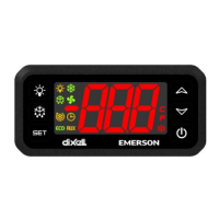
Explains the meaning and function of various icons displayed on the device interface.
Describes the touch gestures used for device navigation and operation.
Explains how to browse through screens using horizontal swipes and timeouts.
Details how to activate standby mode and its effect on device outputs.
Instructions on how to unlock and enter the programming menu for configuration.
Explains how to enter and modify the setpoint value using the SET icon.
Covers procedures for uploading and downloading device configurations using the HotKey.
Describes how to create custom parameter labels using the X9 screen and swipe gestures.
Details how to access and navigate through different parameter groups and settings.
Explains how to set or enter a password to protect access to certain parameters.
Covers electrical shock hazards, proper handling, and environmental considerations for safe operation.
Information on the proper disposal of electrical and electronic waste according to regulations.
Provides detailed explanations for all device parameters, grouped by function.
Details parameters for primary temperature control, compressor differentials, and delays.
Configuration options for selecting and calibrating temperature probes (NTC, PTC, PT1000).
Parameters controlling display units, resolution, and default probe display.
Settings for controlling defrost modes, types, intervals, and durations.
Parameters for managing evaporator and condenser fan operation modes, delays, and settings.
Configuration for auxiliary outputs, including control type, setpoint, and differential.
Settings for configuring temperature alarms, differentials, and delays.
Configuration of digital and analog output relays for various functions like compressor, defrost, and alarms.
Settings for configuring digital inputs for functions such as door switch, defrost activation, and energy saving.
Parameters related to energy saving modes, algorithms, temperature differentials, and light control.
Parameters tracking relay activations, working hours, and digital input counts.
Parameters for setting the clock, day of week, weekend days, and defrost schedules.
Settings for managing configurations, restoring factory defaults, and resetting HACCP values.
Configuration of serial communication settings like device address and baudrate for Modbus communication.
Parameters for configuring button functions, interface timeout, and sound level.
Parameters for visualizing probe values, firmware release, and parameter map version.
Configuration for managing two compressors based on parameters like 2CC and rCC.
Explanation of the energy saving algorithm and parameters like ErA, HES, and HYE.
Describes methods for controlling defrost operations, including timed and temperature-controlled modes.
Details the interaction between evaporator fan control and digital inputs like the door switch.
Configures digital outputs for main compressor and defrost functions.
Configures digital outputs for evaporator fan and alarm signalling.
Configures digital outputs for light control and auxiliary functions, including regulator and timed activation.
Configures door switch input for output control and start defrost input for cycle initiation.
Configures digital inputs for external alarms and energy saving mode activation.
Covers digital inputs for fan mode, holiday mode, remote on/off, light, pull down, motion sensor, and configuration change.
Describes how probe alarms and other alarms are automatically reset or manually cleared.
Wiring diagram for the XR70T model, showing power supply and output connections.
Wiring diagram for the XR60T model, showing power supply and output connections.
Wiring diagram for the XR30T model, illustrating power supply and output connections.
Wiring diagram for the XR20T model, showing power supply and output connections.
Description of optional tools like XH-REP, X-MOD, WIZMATE, HOT-KEY, and USB to RS485 converter.
Details the remote display, motion sensor, and configuration software for the controller.
Explains HOT-KEY for parameter management and USB to RS485 converter for network monitoring.
| Brand | Emerson |
|---|---|
| Model | Dixell XR70T |
| Category | Controller |
| Language | English |
