Pin Definition Function Contact sequence
Pin 12 RS485- RS485- 3
Pin 13 Address bit 4 Address 3
Pin 14 NC Not connected 3 (reserved)
Pin 15 RS485+ RS485+ 3
Pin 16 Address GND Address GND 3
See Fig.1 Pre-charge Precharge 1
See Fig.1 DC+ Output 48V+ 2
See Fig.1 DC+ Output 48V + 2
See Fig.1 DC- Output 48V - 2
See Fig.1 DC- Output 48V - 1
Explanations:
1. Load share+ and Load share- are load-sharing signal cables when
multiple modules work in parallel. They should be well grounded and
shorter than 0.5m.
2. Pre-charge is the signal cable protecting pins upon online
removal/insertion.
3. GND is the module terminal connecting ground. Use yellow-green
bicolor cable with sectional area of 4mm2 or more. Connect it to the
ground reliably.
4. L and N are the live line and neutral line of AC input.
5. Address explanation: The address range of the module is within 0
~ 31. Address bit 0 ~ address bit 4 can be suspended or connect to
GND outside module. Suspending presents 0, and short to GND
presents 1. For example, if Address bit 0 is shorted with GND
outside the module and other addresses are suspending, the module
address is 1.
6. Pin5 and Pin6 are used to limit the output current and report
module model. The module will output according to the external
characteristic of EPW50-48A module and send 0x02 (EPW50-48A)
to the monitoring module when the pin5 and pin6 are shorted from
the back board on the subrack. Otherwise, the module will output
according to the external characteristic of EPW30-48A module and
send 0x01 (EPW30-48A) to the monitoring module.
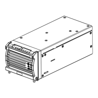
6 Installation And Operation
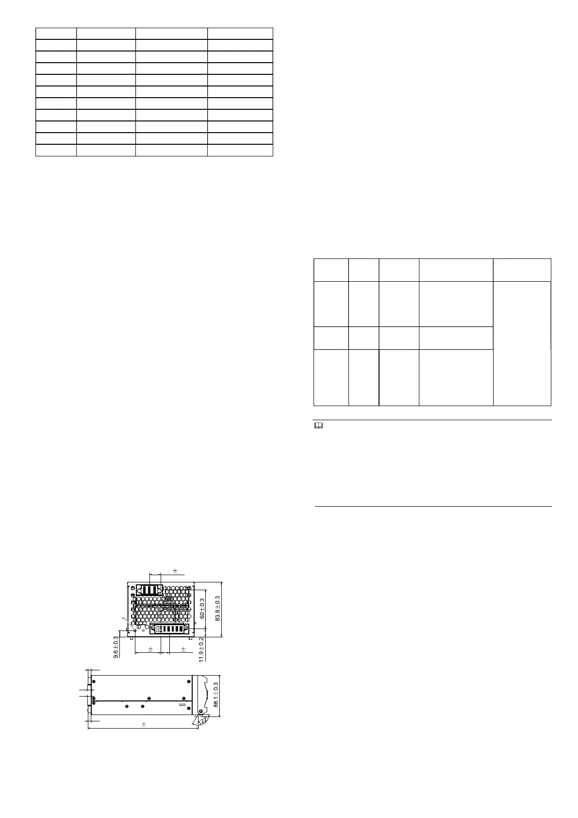
The installation dimensions refer to Figure 2. Install the module using
the following procedures:
1. Make sure the handle of the module is open.
2. Put the module into the corresponding slot.
3. Push the module until the module interfaces contact the interfaces
on the backboard.
4. Push the handle until the module is completely inserted into the
subrack. At this point, the handle tilts up slightly locking the module
into the subrack.
5. Fix the screws on the handle using a screwdriver to finish the
module installation.
17.7 0.2
39.8 0.3 12.9 0.2
Positioring screw
7
7
5.6
230 0.3
Figure 2 Installation dimensions (mm)
Where a single module cannot meet the load demand, multiple
modules can be connected in parallel to share the load. In this case,
just connect all the output connectors and load sharing cables of the
modules respectively in parallel.
7 Maintenance
The module is hot-swappable. The damaged module can be
replaced during the system operation. Locate the module pins in the
backboard socket when replacing the module. Check whether the
pins are bent or skew when the module can not be inserted into the
socket properly.
Replacing the module: the module has a lock structure matching the
external chassis to lock the module in place. When taking out the
module, just pull up the handle on the bottom of the module front
panel and pull it out. When installing the module, insert the module
along the slot smoothly until the lock structure locks the module.
The whole unit should be replaced if maintenance is needed.
8 Troubleshooting
You may contact the nearest Emerson local sales office or service
center if the unit is faulty. Do not manage by yourself. Please return
the faulty unit to Emerson directly for repair. Table 3 is
troubleshooting of simple problems.
Table 3 Troubleshooting
Indicator Normal Abnormal
Reason for
abnormal
Actions
Green
LED
On Off
No AC input, or input
fuse damaged, or
module failure, or all
protections
Red LED Off On
Module shutdown
fault
Yellow
LED
Off On
Module temperature
pre-alarm or the
monitoring module
controls the module
to switch off
Check loads,
input voltage,
input fuse, and
the fan of the
module;
Remove the
conditions
raising
protections
Caution
1
. For continued protection against risk of fire, replace only with
same type and rating of fuse.
2. Double pole / neutral fusing.
3.An air breaker, advisably of 220V/32A or higher rating, should be
installed upstream the module.
4. Specifications are subject to change without notice.
5. Warranty period: 1 year.
Emerson Network Power Co., Ltd.
Address: No.1 Kefa Rd., Science & Industry Park, Nanshan District
518057, Shenzhen China
Homepage: www.emersonnetworkpower.com.cn
E-mail: support@emersonnetwork.com.cn
Copyright © 2009 by Emerson Network Power Co., Ltd.
All rights reserved. The contents in this document are subject to
change without notice.
Version V1.0
Revision date February 23, 2009
BOM 31012061
2
Free Datasheet http://www.datasheet4u.com/
 Loading...