44 70 10170.
website: https://www.add-furnace.com/ 02-888-3472
Line ID: @add11 e-mail: add028883472@gmail.com
Table 1. Outlet Pressure Ranges and Spring Selection
O
u
T
l
ET PRESS
u
RE R
ang
E
(1)
, PSI
g
(bar)
3 to 15
3 to 20
5 to 35
30 to 60
35 to 100
80 to 150
(2)
(0,21 to 1,03)
(0,21 to 1,38)
(0,34 to 2,41)
(2,07 to 4,14)
(2,41 to 6,90)
(5,52 to 10,3)
(2)
1D892327022
1D751527022
1D665927022
1D745527142
1E543627142
1P901327142
Red
Silver
Blue
Green
Yellow
Brown
1. All springs can be backed off to 0 psig (0 bar). For the highest capacity and most accurate control, use the lowest-range spring that can be adjusted to the required setpoint.
2. �annot be used in anhydrous ammonia (NH
3
) applications.
1. Use qualified personnel when installing, operating,
and maintaining these regulators. Before installation
inspect for damage. Make sure there is not any
foreign material in the regulator and all tubing and
piping are clean and unobstructed.
2. If installing the regulator at an outside location,
point the spring case vent in the downward direction
to protect it from getting plugged or from collecting
moisture, corrosive chemicals, or other foreign
materials. Spring case vent orientation may be
changed by rotating the spring case with respect to the
regulator body.
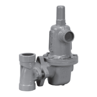
3. Install the regulator so that flow is from the IN to
OUT connection as marked on the regulator body.
!
WaRnIng
If using this regulator on hazardous
gas or flammable fluid, make sure
that the vented gas is piped to a safe,
well-ventilated area. Do not install a
regulator so that the gas will be vented
into a closed space. This could result
in a fire or explosion which could cause
personal injury or equipment damage.
4. To remotely vent the spring case, remove the
screen, if present, and connect 1/4-inch NPT piping
or tubing to the spring case connection. The piping or
tubing should vent the spring case to a safe location,
have as few bends as possible, and have a screened
vent on its exhaust end that is weather resistant and
always pointed in the downward direction.
5. Like most regulators, 64 Series regulators have
outlet pressure ratings lower than inlet pressure
ratings. Although types with internal relief include
limited downstream overpressure protection, all
types may require additional relief protection for
some service conditions if the actual inlet pressure
can exceed the regulator outlet pressure rating or
the pressure ratings of any downstream equipment.
Inspect a regulator periodically and after any
overpressure condition.
6. Each regulator is factory-set for the pressure
setting specified on the order. If no setting is specified,
outlet pressure is factory-set at the midrange of the
control spring.
Startup
Key numbers are referenced in Figure 2.
1. Slowly open the upstream and downstream
shutoff valves while monitoring the outlet pressure
with a gauge installed at some point downstream
from the regulator. Pressure may also be monitored
by installing a pressure gauge in the unused
outlet connection.

 Loading...