EasyManua.ls Logo

Emerson FISHER 657 User Manual

Emerson FISHER 657
32 pages
To Next Page IconTo Next Page
Page #1 background imageLoading...
Page #1 background image
www.Fisher.com
Fisher
657 Diaphragm Actuator
Sizes 30/30i through 70/70i and 87
Contents
Introduction 1.................................
Scope of Manual 1.............................
Description 2.................................
Specifications 2...............................
Educational Services 3.........................
Instructional Videos 3..........................
Installation 3..................................
Mounting the Actuator on the Valve 4............
Discussion of Bench Set 5.......................
Spring Verification 6...........................
Installing the Stem Connector Assembly 7.........
Friction Discussion 9...........................
Deadband Measurement 10.....................
Loading Connection 10.........................
Maintenance 11................................
Actuator Maintenance 11.......................
Top‐Mounted Handwheel Assembly 13...........
Side‐Mounted Handwheel for Sizes 34/34i
through 60/60i Actuators 15..................
Side‐Mounted Handwheel for Sizes 70
and 87 Actuators 17.........................
Casing‐Mounted Adjustable Travel Stops 19.......
Parts Ordering 22...............................
Parts Kits 22...................................
Kits for Side‐Mounted Handwheels 22............
Kits for Top‐Mounted Handwheels 22.............
Parts List 23...................................
Actuator Assembly (figures 6, 7, 8, 9, or 10) 23.....
Figure 1. Fisher 657 Actuator Mounted
on an easy‐e™ Valve
X1175
Top‐Mounted Handwheel (figures 11 or 12) 23.....
Side‐Mounted Handwheel (figure 13 or 17) 26.....
Casing‐Mounted Adjustable Up Travel Stops
(figures 18 or 19) 31.........................
Casing‐Mounted Adjustable Down Travel Stops
(figure 20) 32..............................
Introduction
Scope of Manual
This instruction manual provides information on installation, adjustment, maintenance, and parts ordering for the
Fisher 657 actuator in sizes 30/30i through 70/70i and size 87. The 657‐4 actuator in sizes 70/70i and 87 is also
covered. Refer to separate instruction manuals for information about the valve positioner and other accessories used
with these actuators.
Do not install, operate, or maintain a 657 actuator without being fully trained and qualified in valve,actuator, and
accessory installation, operation, and maintenance. To avoid personal injury or property damage, it is important to
carefully read, understand, and follow all the contents of this manual, including all safety cautions and warnings. If you
have any questions about these instructions, contact your Emerson sales office
or Local Business Partner before
proceeding.
Instruction Manual
D100306X012
657 Actuator (30/30i-70/70i and 87)
June 2018
Question and Answer IconNeed help?

Do you have a question about the Emerson FISHER 657 and is the answer not in the manual?

Emerson FISHER 657 Specifications

General IconGeneral
ActionDirect or reverse
Actuator TypeDiaphragm
Input Signal3-15 psi
Temperature RangeSee Operating Temperatures
Spring Ranges3-15 psi

Summary

Introduction and Overview

Scope of Manual

Outlines the manual's coverage for Fisher 657 actuators.

Description

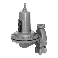
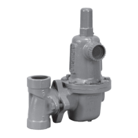
Details the Fisher 657 diaphragm actuator and its functions.

Specifications

Lists technical specifications for the 657 and 657-4 actuators.

Educational Services

Provides information on available training courses and resources.

Instructional Videos

Offers links to video guides for actuator installation and setup.

Installation

General guidance for installing the actuator on the valve.

Actuator Mounting and Connection

Mounting the Actuator on the Valve

Steps for physically attaching the actuator to the valve body.

Installing the Stem Connector Assembly

Procedure for connecting the actuator and valve stems.

Bench Set and Spring Adjustment

Discussion of Bench Set

Explains bench set pressure for initial spring adjustment.

Spring Verification

Verifies the correct spring compression for actuator travel.

Actuator Performance Factors

Friction Discussion

Details how to account for friction in actuator adjustments.

Deadband Measurement

Procedure to measure actuator deadband for loop control.

Loading Connection

Loading Connection

Instructions for connecting the pneumatic loading pressure.

Maintenance and Assembly

Actuator Maintenance

General guidelines for actuator inspection and upkeep.

Actuator Disassembly

Step-by-step guide for taking the actuator apart.

Actuator Assembly

Step-by-step guide for reassembling the actuator.

Handwheel Assemblies

Top-Mounted Handwheel Assembly

Information on the top-mounted handwheel, used as a travel stop.

Disassembly for Top-Mounted Handwheel

Steps to take down the top-mounted handwheel assembly.

Assembly for Top-Mounted Handwheel

Steps to put together the top-mounted handwheel assembly.

Side-Mounted Handwheel for Sizes 34-60 and 34i-60i Actuators

Details for side-mounted handwheels on specific actuator sizes.

Disassembly for Side-Mounted Handwheel (Sizes 34-60 and 34i-60i)

Steps to take down side-mounted handwheels for specific sizes.

Assembly for Side-Mounted Handwheel (Sizes 34-60 and 34i-60i)

Steps to put together side-mounted handwheels for specific sizes.

Side-Mounted Handwheel for Sizes 70 and 87 Actuators

Details for side-mounted handwheels on larger actuator sizes.

Disassembly for Side-Mounted Handwheel (Size 70 and 87)

Steps to take down side-mounted handwheels for sizes 70 and 87.

Assembly for Side-Mounted Handwheel (Size 70 and 87)

Steps to put together side-mounted handwheels for sizes 70 and 87.

Travel Stops

Casing-Mounted Adjustable Travel Stops

Information on adjustable travel stops mounted on the actuator casing.

Casing-Mounted Adjustable Up Travel Stops

Procedure for adjusting upward travel limits.

Casing-Mounted Adjustable Down Travel Stops

Procedure for adjusting downward travel limits.

Disassembly for Casing-Mounted Travel Stop

Steps to disassemble casing-mounted travel stops.

Parts and Ordering

Parts Ordering

Guidance on how to order replacement parts.

Kits for Side-Mounted Handwheels

Specific kits for adding side-mounted handwheels.

Kits for Top-Mounted Handwheels

Specific kits for adding top-mounted handwheels.

Transition Kits for Side-Mounted Handwheels

Kits for adapting handwheels to changed yoke sizes.

Parts List

Comprehensive list of actuator components and their numbers.

Related product manuals