EasyManua.ls Logo

Emerson Fisher 630 Series User Manual

Emerson Fisher 630 Series
12 pages
To Next Page IconTo Next Page
Page #1 background imageLoading...
Page #1 background image
630 Series
D100300X012
December 2015
Instruction Manual
Form 1243
www.fisherregulators.com
630 Series Regulators and Relief Valves
Introduction
Scope of Manual
This Instruction Manual provides operating, installation,
maintenance and parts information for the 630 Series
regulators and relief valves.
Description
The 630 Series consists of self-operated, spring
loaded Type 630 Big Joe
®
pressure regulators and
Type 630R relief valves, which are designed for
maximum inlet pressures to 1500 psig / 103 bar and
outlet pressures from 3 to 500 psig / 0.21 to 34.5 bar.
Installation
!
WARNING
Personal injury, property damage,
equipment damage or leakage due to
escaping gas or bursting of pressure-
containing parts may result if this
regulator is overpressured or is installed
where service conditions could exceed
the limits given in Specications
section, Tables 1 through 3 or where
conditions exceed any ratings of the
adjacent piping or piping connections.
To avoid such injury or damage, provide
pressure-relieving or pressure-limiting
devices (as required by the appropriate
code, regulation or standard) to prevent
service conditions from exceeding
those limits.
Additionally, physical damage to the
regulator could cause personal injury or
property damage due to escaping gas.
To avoid such injury or damage, install
the regulator in a safe location.
Before installing, inspect the unit for any damage and
any foreign material. The regulator or relief valve may
be mounted in any position, however, ensure that the
ow direction corresponds with the direction of the
arrow on the nameplate. Apply a good grade of pipe
compound to the male threads of the pipeline.
Figure 1. Spring-Loaded Type 630 Regulator
W1934
Question and Answer IconNeed help?

Do you have a question about the Emerson Fisher 630 Series and is the answer not in the manual?

Emerson Fisher 630 Series Specifications

General IconGeneral
Trim MaterialStainless Steel
End Connection StyleNPT
Temperature Capabilities-40°F to 250°F (-40°C to 121°C)
Body MaterialStainless Steel
Input SignalPneumatic
Supply Pressure20 psig (1.4 bar) above maximum regulated pressure
Ambient Temperature Range-20 to 180°F / -29 to 82°C (depending on materials)
CertificationsATEX

Summary

Introduction

Scope of Manual

Details operating, installation, maintenance, and parts for 630 Series regulators/relief valves.

Description

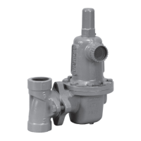
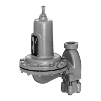
Explains the 630 Series consists of self-operated, spring-loaded regulators and relief valves.

Installation

Specifications

Available Configurations

Lists the Type 630 spring-loaded reducing regulators and Type 630R spring-loaded relief valves.

Technical Specifications

Covers pressure ratings, temperature capabilities, orifice sizes, and weights.

Safety and Operational Notes

Startup

Adjusting Spring-Loaded Regulators and Relief Valves

Shutdown and Principle of Operation

Shutdown

Procedure for safely shutting down the regulator or relief valve.

Principle of Operation

Explains how pressure affects diaphragm and lever action for Type 630/630R.

Maintenance

Replacing Orifice, Valve Disk and Lever

Step-by-step guide for removing and replacing the orifice, valve disk, and lever components.

Replacing the Diaphragm

Parts Ordering

Parts List

Parts Kits

Details available kits for Type 630 regulators, including diaphragm, gasket, and disk materials.

Related product manuals