!
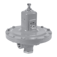
INDICATOR COVER
(KEY 21)
HEX NUTS
(KEY 4)
INDICATOR FITTING
(KEY 19)
O-RING
(KEY 18)
UPPER SPRING
SEAT (KEY 17)
MAIN SPRING
(KEY 12)
INDICATOR STEM
(KEY 15)
BACK-UP
RINGS
(KEY 16)
INDICATOR
O-RING (KEY 6)
INDICATOR
WASHER (KEY 20)
W7400_1
WARNING
Type MR98H Pilot Maintenance
To avoid personal injury, property
damage or equipment damage caused
by sudden release of pressure or
uncontrolled process fluid, do not
attempt any maintenance or disassembly
without first isolating the regulator
from system pressure and relieving all
internal pressure from the regulator.
Relief valves or regulators that have been
disassembled for repair must be tested
for proper operation before being returned
to service. Only parts manufactured by
Emerson should be used for repairing
Fisher™ relief valves and regulators.
11. Install the indicator fitting (key 19) into the bonnet
(key 2, Figure 7), tighten to the proper torque
(see Table 11). To set the travel indicator, hold
the indicator cover (key 21) next to the indicator
fitting (key 19). Screw the hex nuts (key 4) and
the indicator washer (key 20) down on the
indicator stem (key 15) until the washer is even
with the lowest marking on the indicator cover.
Lightly lubricate the indicator cover threads and
install. Replace the indicator protector (key 22).
To replace the travel indicator with the non-
travel indicator option, place the main spring
(key 12) into the bonnet. Install the indicator plug
(key 19, Figure 15) and tighten to proper torque
(see Table 11).
Due to normal wear and damage that may occur from
external sources, relief valve parts such as the O-rings,
gaskets, diaphragm, orifice and valve plug should be
inspected periodically and replaced as necessary. The
frequency of inspection and replacement depends upon
the severity of service conditions or the requirements of
state and federal laws.
The following instructions explain the disassembly of
the Type MR98H relief or backpressure pilot. Lightly
apply a good quality lubricant when reassembling. Key
numbers are referenced in Figure 16.
1. Shut down the backpressure regulator or relief valve.
2. Relieve the spring tension by loosening the jam
nut (key 17) and turning the adjusting screw
(key 15) counterclockwise. Remove cap screws
(key 16) and lift off the spring case (key 2), upper
spring seat (key 9) and relief valve spring (key 11).
3. Lift out the diaphragm unit which includes the
lock nut (key 31), lock washer (key 28), pusher
post (key 10), gasket (key 29), lower spring seat
(key 8), diaphragm (key 12), valve plug (key 4)
and an O-ring (key 45).
4. Check the orifice (key 3) for wear or damage. If
it needs to be replaced, unscrew the valve plug
guide (key 7) and then the orifice. The valve plug
(key 4) can be removed by sliding it off of the
pusher post (key 10).
5. Place a small amount of sealant on the threads of
the orifice (key 3) and valve plug guide (key 7) and
reinstall these to the body (key 1).
6. To replace the valve plug O-ring (key 53), remove the
machine screw (key 24) and O-ring retainer (key 25)
from the plug. Remove and replace the O-ring.
Figure 8. Travel Indicator Parts
14
Type LR128
 Loading...


