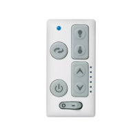
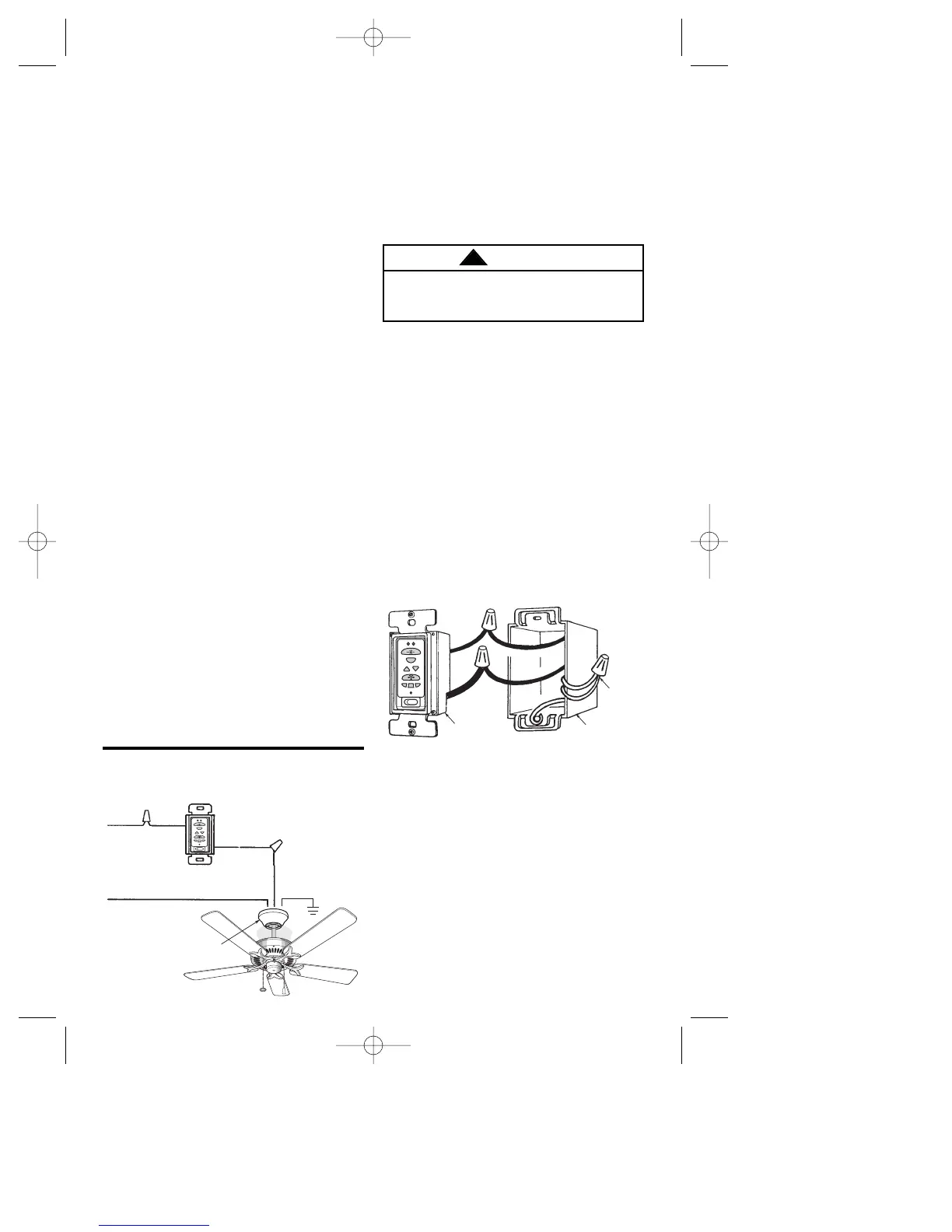
Figure 10
SINGLE-POLE INSTALLATION (Figure 10)
1. Disconnect power at circuit breaker or
remove fuse.
2. Remove faceplate and screws from
existing wall switch. Pull switch out
from the wall box. Do not attempt to
disconnect any wires not already
connected to existing switch.
3. Connect one black wire of wall control
to the “hot” wire in the wall box.
Securely connect wires with wire
connectors supplied (Figure 11).
4. Connect the other black wire of wall
control to the “load” (black) wire in wall
box. Securely connect wires with wire
connector supplied.
5. Screw wall control into wall box and
install decorator style faceplate
(included). Leave wall control in “OFF”
mode until fan installation is completed.
6. Refer to fan Owner’s Manual to
complete fan installation.
7. Perform Code Learning Procedure
(Page 8).
Do not connect any neutral (white) wire
to this control. Incorrect wiring will
damage this control.
WARNING
!
Figure 11
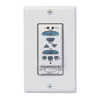
3-WAY INSTALLATION
(One fan controlled by two different
wall controls) (See Figures 12 and 13.)
1. Disconnect power at circuit breaker or
remove fuse.
2. At all wall box locations remove
faceplates and screws from existing
switches. Pull switches out from wall
boxes and determine which wall box
contains the “hot” lead and which wall
box contains the “load” wire. Also,
identify traveler wire(s) which are
common to both wall boxes.
16. Connect the black wire from the
wiring harness to the black (hot)
supply wire (Figure 5). Connect the
white wire from the wiring harness to
the white (neutral) supply wiring.
Connect the green ground wires from
the hanger bracket and the hanger
ball to the supply ground wire. Use
wire connectors supplied with your
ceiling fan.
17. Securely connect the wiring harness
connector to the receiver connector,
and connect the blue and yellow wires
(yellow wire is used only on a fan with
a built in Uplight) to the blue and yellow
wires from the receiver (Figure 5).
18. Fold and position the wires into the
space above the hanger ball and into
the outlet box (Figure 9).
19. Feed the wires and connectors
through the open side of the hanger
bracket, and into the outlet box. Slide
the receiver up and over the hanger
bracket. Press the receiver against
the ceiling holding it in place while
installing the ceiling cover in
accordance with the instructions in
the ceiling fan Owner's Manual.
20. Install the fan blades in accordance
with the instructions in the ceiling fan
Owner’s Manual.
NOTE 7: On Model CF2454, CF2600,
CF2650, and CF2675 Series Ceiling
Fans, install the light fixture assembly
(supplied) in accordance with the
instructions in the ceiling fan owner’s
manual.
21. Install the optional downlight kit in
accordance with the instructions in
the downlight kit Owner’s Manual.
 Loading...