EasyManua.ls Logo

Emerson White Rodgers 50A65-5165 - User Manual

Emerson White Rodgers 50A65-5165
8 pages
Print Icon
To Next Page IconTo Next Page
Loading...
Trane White-Rodgers
CNT05164 50A65-475
CNT05165 50A65-476
50A65-5165
50A65-5165
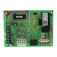
Integrated Furnace Control
FAILURE TO READ AND FOLLOW ALL INSTRUCTIONS CAREFULLY BEFORE
INSTALLING OR OPERATING THIS CONTROL COULD CAUSE PERSONAL
INJURY AND/OR PROPERTY DAMAGE.
DESCRIPTION
INSTALLATION INSTRUCTIONS
The 50A65-5165 is an automatic gas interrupted
ignition control that employs a microprocessor to
continually monitor, analyze, and control the proper
operation of the gas burner, inducer, and fan.
Signals interpreted during continual surveillance of
the thermostat and flame sensing element initiate
automatic ignition of the burner, sensing of the flame,
and system shut-off during normal operation.
These controls incorporates system fault analysis for
quick gas flow shut-off, coupled with automatic ignition
retry upon sensing a fault correction. It is designed as a
replacement for the following controls:
PRECAUTIONS
Installation should be done by a qualified heating and
air conditioning contractor or licensed electrician.
If in doubt about whether your wiring is millivolt, line, or
low voltage, have it inspected by a qualified heating and
air conditioning contractor or licensed electrician.
Do not exceed the specification ratings.
All wiring must conform to local and national electrical
codes and ordinances.
This control is a precision instrument, and should
be handled carefully. Rough handling or distorting
components could cause the control to malfunction.
Following installation or replacement, follow
manufacturer’s recommended installation/service
instructions to ensure proper operation.
white-rodgers.com
emersonclimate.com
PART NO. 37-7516B
Replaces 37-7516A
1515
CAUTION
!
Do not short out terminals on gas valve or primary
control. Short or incorrect wiring may damage
the thermostat.
WARNING
!
Failure to comply with the following warnings could
result in personal injury or property damage.
FIRE HAZARD
Do not exceed the specified voltage.
Replace existing control with exact model and
dash number.
Protect the control from direct contact with water
(dripping, spraying, rain, etc.).
If the control has been in direct contact with
water, replace the control.
• Label all wires before disconnection when
servicing controls. Wiring errors can cause
improper and dangerous operation.
Route and secure wiring away from flame.
SHOCK HAZARD
Disconnect electric power before servicing.
Ensure proper earth grounding of appliance.
Ensure proper connection of line neutral and
line hot wires.
EXPLOSION HAZARD
Shut off main gas to appliance until installation
is complete.

Questions and Answers

  • J
    John LewisAug 15, 2025
    How to fix external lockout (exceeded retries) in Emerson Control Systems?
    • B
      Brian SmithAug 15, 2025
      If your Emerson Control Systems experiences an external lockout due to exceeding retries, it's often because the flame sensor isn't detecting the flame. This can be due to carbon buildup on the sensor, a disconnected or shorted sensor lead, or poor grounding. Clean carbon deposits using emery cloth. Ensure the sensor isn't touching the burner and is well-positioned to sense the flame. Check the sensor lead for shorts and confirm the furnace is properly grounded. Also, verify the gas supply to the valve, the gas valve's 'On' position, proper appliance lighting, flame reaching the sensor during ignition, and correct gas pressures.
  • C
    Cathy GuerraAug 18, 2025
    What to do if Emerson Control Systems shows low flame sense current?
    • J
      Jesse ShieldsAug 18, 2025
      If your Emerson Control Systems shows a low flame sense current, it's often due to carbon deposits on the flame sensor, a poorly grounded furnace, or a misaligned flame sense probe. You can clean carbon deposits with emery cloth. Check or improve the furnace and module ground. Make sure the sensor is located in or very near the flame as specified by the appliance manufacturer. Refer to wiring diagram FS terminal and GND.
  • L
    Lisa StaffordAug 21, 2025
    What causes gas valve circuit error in Emerson Control Systems and how to fix it?
    • C
      Carla EnglishAug 21, 2025
      If you have a gas valve circuit error in your Emerson Control Systems, this indicates the gas valve relay contacts on the ignition module are not functioning properly. To resolve this, replace the ignition module.
  • L
    Lisa MartinezAug 25, 2025
    What to do if flame sensed with gas valve de-energized in Emerson Control Systems?
    • S
      Sarah HallAug 26, 2025
      If your Emerson Control Systems has flame sensed with the gas valve de-energized, verify the gas valve is operating and shutting down properly. The flame in the burner assembly should extinguish promptly at the end of the cycle. Check orifices and gas pressure.
  • Z
    Zachary BrownAug 28, 2025
    How to check reversed polarity in Emerson Control Systems?
    • A
      Alex FreemanAug 28, 2025
      If your Emerson Control Systems has reversed polarity, verify the control and furnace are properly grounded. Check and reverse polarity (primary or secondary) if incorrect.
  • J
    joann87Aug 31, 2025
    How to check open high temperature limit switch in Emerson Control Systems?
    • A
      Ashley FernandezAug 31, 2025
      If your Emerson Control Systems has an open high temperature limit switch, verify continuity through the limit switch circuit. Refer to wiring diagram terminals, HLO.
  • D
    dylansawyerSep 4, 2025
    What to do if pressure switch problem, vent on Inducer problem in Emerson Control Systems?
    • C
      Carl PattersonSep 4, 2025
      If you're facing a pressure switch problem or vent on Inducer problem with your Emerson Control Systems, check the switch function and verify the inducer is working correctly. Refer to wiring diagram, terminals PS.
  • J
    James CohenSep 7, 2025
    How to verify control failure in Emerson Control Systems?
    • N
      Nancy GraySep 7, 2025
      If your Emerson Control Systems experiences a control failure, verify power to the control.
  • K
    Kathleen CollinsSep 12, 2025
    How to fix control failure in Emerson Control Systems?
    • J
      Joseph MarshSep 12, 2025
      If your Emerson Control Systems experiences a control failure, replace the IFC.

Summary

White-Rodgers 50 A65-5165 Furnace Control

General Safety Precautions

Highlights warnings for Fire, Shock, and Explosion hazards, including electrical safety and gas shut-off.

Control Specifications

Flame Sensing Requirements

Specifies minimum and maximum current for flame detection and allowable leakage resistance.

System Safety Warnings

Reinforces warnings for Fire, Shock, and Explosion hazards, emphasizing proper installation and handling.

System Wiring

Wiring Details

Operation Modes and Settings

Ignition and Retry Sequence

Explains the ignition process, flame detection, delay periods, and the retry sequence for ignition failures.

Flame Loss and Lockout

Describes how flame loss is handled, including recycle attempts and system lockout conditions.

Operational Modes and System Features

System Lockout Features

Explains what happens during system lockout and how to reset the control.

Diagnostic Features and LED Indicators

Details how the control monitors operation and uses an LED to indicate status or failure codes.

Troubleshooting Guide

LED Flash Error Codes

Lists LED flash patterns and their corresponding error conditions and troubleshooting comments.

Common Error Conditions

Details common issues like external lockout, pressure switch problems, and flame sensing failures.

Emerson White Rodgers 50A65-5165 Specifications

General IconGeneral
BrandEmerson
ModelWhite Rodgers 50A65-5165
CategoryControl Systems
LanguageEnglish

Related product manuals