EasyManua.ls Logo

Emerson White Rogers SureSwitch 49P11-843 User Manual

Emerson White Rogers SureSwitch 49P11-843
12 pages
To Next Page IconTo Next Page
Page #1 background imageLoading...
Page #1 background image
49P11-843
Emerson SureSwitch™
PART NO. 37-7295B
Replaces 37-7295A
1304
INSTALLATION INSTRUCTIONS
FAILURE TO READ AND FOLLOW ALL INSTRUCTIONS CAREFULLY BEFORE
INSTALLING OR OPERATING THIS CONTROL COULD CAUSE PERSONAL INJURY
AND/OR PROPERTY DAMAGE.
PRECAUTIONS
CONTENTS
Description ....................................................................... 1
Precautions ....................................................................... 1
Specications ................................................................... 2
Mounting .......................................................................... 2
Quick Reference ................................................................... 2
Operation ......................................................................... 3
Troubleshooting ............................................................... 3
Wiring Diagram .................................................................... 4
DESCRIPTION
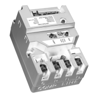
SureSwitch™ is an electronically-controlled relay that can be used
to replace single and two-pole contactors commonly used in air
conditioners, heat pumps and other applications. A patented switching
algorithm reduces arcing between contacts, which nearly eliminates
pitting and welding for a longer life. The switching mechanism is sealed
to prevent intrusion from insects and other debris.
SureSwitch also provides advanced features for HVAC troubleshooting
and system reliability:
• Line-VoltageBrownoutProtection
• ShortCycleProtection
• RandomStartDelay
• LifetimeCycleCount
SureSwitch is similar to a 1
1
/
2
pole contactor, in that only the
compressor terminal C is switched. The compressor terminal R is
connected by a shorting bar to line input L1, and is energized even
when a call is not present.
Installationshouldbedonebyaqualiedheatingandairconditioning
contractor or licensed electrician.
Donotexceedthespecicationratings.
All wiring must conform to local and national electrical codes and
ordinances.
This control is a precision instrument, and should be handled carefully.
Roughhandlingordistortingcomponentscouldcausethecontrolto
malfunction.
Following installation or replacement, follow manufacturer's
recommended installation/service instructions to ensure proper
operation.
SureSwitchhasnouserserviceableparts.Replaceasaunit.
www.white-rodgers.com
www.emersonclimate.com
Operator: Save these instructions for future use!
Failure to comply with the following warnings could result
in personal injury or property damage.
FIRE HAZARD
• Donotexceedthespeciedvoltage.
• Replaceexistingcontrolwithexactmodelanddash
number.
• Protectthecontrolfromdirectcontactwithwater
(dripping, spraying, rain, etc.).
• Ifthecontrolhasbeenindirectcontactwithwater,
replace the control.
• Labelallwiresbeforedisconnectionwhenservicing
controls. Wiring errors can cause improper and
dangerous operation.
• Safetyrouteandsecurewiringafterinstallation.
SHOCK HAZARD
• Disconnectelectricpowerbeforeservicing.
• Ensureproperearthgroundingofappliance.
• Ensureproperconnectionoflineneutralandlinehot
wires.
• Compressoroutput"R"isnotswitchedandis
energized at all times.
WARNING
!

Questions and Answers:

Emerson White Rogers SureSwitch 49P11-843 Specifications

General IconGeneral
TypeElectromechanical Relay
Model Number49P11-843
Coil Voltage24 VAC
Electrical Life100, 000 cycles
Mechanical Life1, 000, 000 cycles
MountingPanel Mount
BrandEmerson
Contact Rating10A
Termination TypeQuick Connect
Contact FormSPST-NO (Single Pole Single Throw - Normally Open)

Summary

Product Description and Features

SureSwitch Overview

Overview of SureSwitch as an electronic relay for HVAC applications, highlighting its features and benefits.

Advanced HVAC Features

Lists advanced features like brownout protection, short cycle protection, random start delay, and lifetime cycle count.

Safety Precautions and Warnings

General Safety Warning

General warning about potential personal injury or property damage if instructions are not followed.

Fire Hazard Warnings

Outlines fire hazards such as exceeding voltage limits, improper wiring, and water contact.

Electrical Shock Hazard Warnings

Details shock hazards including power disconnection, grounding, and correct wire connections.

Technical Specifications and Mounting

Electrical Ratings

Lists voltage, current (FLA, LRA) ratings for the SureSwitch device.

Terminal Torque Specifications

Specifies recommended torque values for connecting terminals L1, L2, R, and C.

Mounting Instructions

Step-by-step guide for installing the SureSwitch, including power disconnection and wiring.

Two Piece Design Diagram

Illustration showing the two-piece design of the SureSwitch device.

Terminals and Switches Diagram

Diagram identifying terminals, switches, and indicators on the SureSwitch.

Typical Electrical Wiring Diagram

Shows the electrical connections for the SureSwitch in a typical circuit.

Operation Modes and Features

Compressor Operation Trigger

Explains how a 24 VAC signal between Y and C initiates compressor operation.

System Test Mode

Describes the Test Mode for energizing compressor and fan for troubleshooting.

Random Start Delay Function

Details the 5-90 second random start delay activated on power-up or brownout recovery.

Short Cycle Protection

Explains the 3-minute delay to prevent compressor damage from rapid cycling.

Line Voltage Brownout Protection

Describes how brownout protection de-energizes the compressor below specific voltage thresholds.

Lifetime Cycle Count Feature

How to view the total number of compressor cycles stored in memory.

LED Status Codes

Lists and explains the meaning of different LED color and flash codes.

Troubleshooting Guide

Common Symptoms and Causes

Lists common operational symptoms, their possible causes, and corrective actions.

Wiring Diagram

Typical Wiring Diagram for HVAC Systems

Illustrates typical wiring for 4-wire and 3-wire condenser fans with SureSwitch.

Wiring Legend and Components

Defines line voltage, low voltage, optional circuits, and components in the diagrams.

Related product manuals