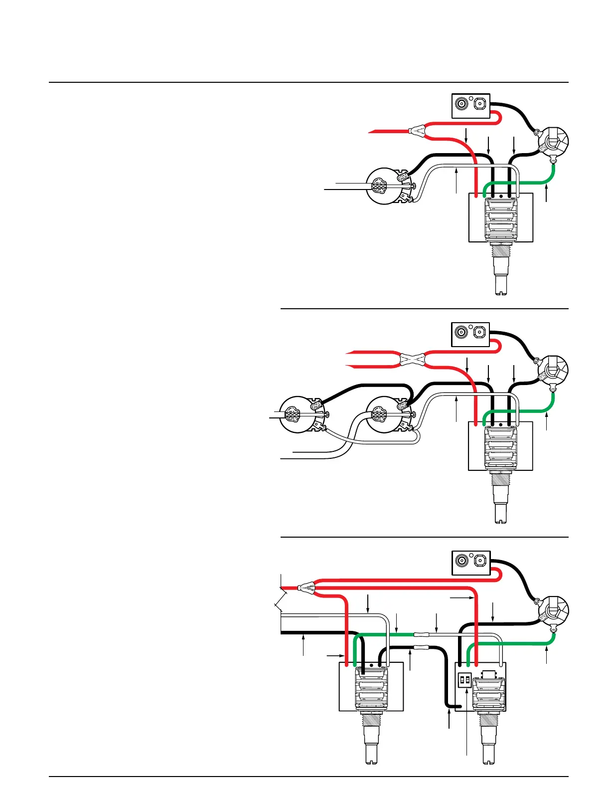
1 Volume
1 VMC
Red
White
Black
Green
2 Volume
1 VMC
Black
Red
White
Green
VMC with BTC
Red
White
Black
Green
Green
Black
Black
Black
High Frequency
Selector Switch
Red
White
ONON
12
VMC BTC
Unsolder and remove the tone control and its
capacitor. Also remove the black wires going
from the tone control to the jack and from the
tone control to the volume control. They won't be
reconnected.
Unsolder and remove the "Hot" wire that con-
nects between the outer lug of the jack (tip) and
the volume control.
Mount the VMC CONTROL in the instrument.
Solder the white wire of the VMC CONTROL to
the volume control as shown in the diagram.
Solder the green wire of the VMC CONTROL to
the jack (tip) as shown in the diagram.
Solder one black wire from the VMC CONTROL
to center solder lug (sleeve) on the jack. Solder
the other black wire to the case of the volume
pot as shown in the diagram.
Solder the red wire of the VMC CONTROL
together with the red wires from the pickups and
battery clip. Cover this connection with shrink
tubing.
Attach the battery and test the instrument.
This completes the installation. If you have any
problems, contact the factory at the number pro-
vided on the front page of these instructions.
Service is readily available.
INSTALLATION INSTRUCTIONS
FOR THE VMC CONTROL
1)
2)
3)
4)
5)
6)
7)
8)
9)
This diagram illustrates how to wire the VMC
CONTROL together with a BTC or BTS CON-
TROL. Not shown is the volume pot(s) because
it is wired exactly as shown above.
Solder the white wire and one black of the VMC
CONTROL to the volume pot as shown above.
Solder the other black wire of the VMC CON-
TROL to one black wire of the BTC or BTS
CONTROL. Cover the connection with heat
shrink tube.
Solder the other black wire of the BTC or BTS
CONTROL to the sleeve connection of the out-
put jack as shown in the diagram.
Solder the green wire of the VMC CONTROL to
the white wire of the BTC or BTS CONTROL.
Cover the connection with heat shrink tube.
Solder the green wire of the BTC or BTS CON-
TROL to the tip connection of the output jack as
shown in the diagram.
Solder the red wire of the VMC CONTROL
together with the red wires from the BTC or BTS
CONTROL, the pickups and the battery clip.
Cover this connection with heat shrink tubing.
This completes the installation. If you have a
problem contact the factory at the number on the
front of these instructions. Service is readily
available.
INSTALLATION INSTRUCTIONS
FOR THE VMC CONTROL
WITH THE BTC OR BTS CONTROL
6)
5)
4)
3)
2)
1)
7)
 Loading...