This document describes the DIZ Generation G digital industrial meter, a versatile device designed for measuring electrical energy in various network configurations.
Function Description
The DIZ Generation G is a digital single-rate, two-rate, or four-rate tariff meter capable of measuring both positive and negative effective and reactive energy in 2, 3, and 4-wire networks. Tariff switching can be performed either via an internal real-time clock (RTC) or an external control input.
Primarily, the device is intended for energy data collection in industrial engineering, building technology, and the utility sector. In its transformer version, the meter features an adjustable transformer ratio, allowing for the recording of actual energy consumption. This ratio can be adjusted directly on the meter using the control button. For billing purposes, the editing menu can be irrevocably locked, preventing further modification of transformer factors.
Energy consumption values can be output through secondary or primary pulse outputs, or via an electrical two-wire (M-Bus) or RS485 (M-Bus, SML, Modbus-RTU®) interface. The pulse constant and pulse length are adjustable depending on the meter version. The meter can operate as a secondary meter (measuring energy on the secondary side of transformers) or, by setting transformer factors, as a primary meter (measuring actual energy on the primary side of transformers).
Important Technical Specifications
Electrical Data:
- Voltage, current: See name plate
- Utilisation category: UC2 (direct metering meter)
- Overvoltage category: OVC III (as per EN 62052-31)
- Rated peak withstand voltage: 4 kV (as per EN 62052-31)
- Frequency: 50 Hz, 60 Hz
- Control input:
- Low voltage: 5...40 V AC
- System voltage: 58...230 V AC
- Output:
- S0 output: max. 27 V DC, 27 mA (passive)
- Opto-MOSFET: max. 250 V AC/DC, 100 mA
- Power consumption per phase:
- Voltage circuit: < 2.0 VA / 1.0 W
- Current path: < 2.5 VA
Environmental and Mechanical Data:
- Temperature range:
- Defined operating range: -25 °C...+55 °C
- Limit range for operation, storage and transport: -40 °C...+70 °C
- Humidity: Maximum 95%, non-condensing, as per EN 62052-11, EN 50470-1 and EN 60068-2-30
- Altitude: up to 3,000 m
- Protection class: II
- Degree of protection: Housing, terminal block: IP30
- Installation environment: The device may only be used in switch and meter cabinets with a degree of protection of IP51 (or higher), ensuring protection against dust and water as specified by relevant standards (EN 50470-1, EN 62052-31).
- Fire properties: As per EN 62052-31
- Environmental conditions:
- Mechanical: M1 according to the Measuring Instruments Directive (2014/32/EU)
- Electromagnetic: E2 according to the Measuring Instruments Directive (2014/32/EU)
- Intended operating location: Interior as per EN 50470-1
- Weight: Approx. 450 g
Interfaces:
- M-Bus interface: Designed as per DIN EN 13757-2, -3. Galvanically isolated from the meter, located on additional terminals 23 and 24. Parameters transferable include manufacturer identification, medium, primary/secondary M-Bus address, energy values, and instantaneous values (PTotal, individual power values, currents, voltages, reactive power, apparent power, frequency, power factors, neutral conductor current, U and I transformer factors, error status, load profile). Up to 32 devices can be connected, with a maximum cable length of 1,000 m and data transfer rates from 300 to 38400 baud.
- RS485 interface (M-Bus, SML, Modbus-RTU®): Symmetrical two-wire interface (half-duplex) as per TIA/EIA-485/ITU-T V.11. Galvanically isolated from the meter, located on additional terminals 14 and 16. Supports up to 31 meters and 1 modem. Data protocols include M-Bus, SML (version 1.03), and Modbus-RTU®. For SML, the baud rate is permanently set to 9600 baud. Modbus-RTU® allows only the master to initiate data exchange, with up to 247 slaves per interconnection. Transfer rates can be set to 8E1, 8O1, 8N1, and 8N2.
Usage Features
Display and Control:
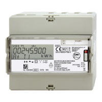
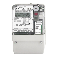
The meter features a display, folding terminal cover, sealing eye, field for transformer plate (for transformer connected meters), test LED, call-up button, name plate, and a catch mechanism on the back.
- Display control: Operated via a call-up button.
- Brief press (t < 2 s): Moves to the next list value, menu item, or setting value; activates display illumination (if equipped).
- Long press (2 s ≤ t ≤ 5 s): Activates the currently displayed menu item; confirms changed settings.
- Longer press (t ≥ 5 s): Returns to the standard operating display.
- Illuminated display (optional): Activated by a brief press of the call-up button. Turns off automatically after 30 s in standard operating display, after 5 mins in menus, or when exiting the call-up menu/pressing the button for ≥ 5 s. Not available in battery mode.
- Error display: Shows error codes in hexadecimal format. If an error is displayed, the meter data must not be used for billing, and device operation may be affected.
- Start list: Upon voltage application, displays firmware version and checksum for 5 s before showing the standard operating display.
- Standard operating display: Shows configuration-specific energy registers for the current tariff at 5 s intervals (scrolling). In battery mode, only tariffs T0 and T1 are shown.
- Call-up menu: Activated by pressing the call-up button. Provides access to tariff information, installation check values, and submenus: tariff list, measurements, device settings, test menu, editing menu, and set menu. In battery mode, only tariff registers and transformer factors are displayed.
Modifiable Parameters (Editing Menu):
If the editing menu is unlocked (indicated by a flashing key symbol), the following parameters can be changed:
- Transformer factors:
- Voltage transformer ratio VT (1 to 999, default 1).
- Current transformer ratio CT (1 to 9999, default 1).
- Product of CT x VT can be a maximum of 999999.
- Changing transformer factors resets energy registers to zero and resets register resolution and pulse constants.
- Arities of the energy registers: Register resolution can be modified via display control or data interface. Possible values depend on direct or transformer connected meters and transformer factor.
- Settings of the pulse outputs: Pulse value can be set to 1, 10, 100, or 1000 pulses/kWh or pulses/kvarh. Configuration is permanently set at delivery and cannot be modified.
Set Menu:
Allows modification of system time, addresses, and baud rate.
- Primary address: 001-250 (M-Bus only).
- Secondary address: 00000000-99999999 (M-Bus only).
- Baud rate of M-Bus: 0300, 2400, 9600 bd.
- Address of Modbus®: 001-247.
- Baud rate of Modbus®: 1200, 2400, 4800, 9600, 19200, 38400 bd.
- Transfer rate of Modbus®: 8E1, 8O1, 8N1, 8N2.
Maintenance Features
Maintenance and Warranty:
- The device requires zero maintenance.
- Repairs are not permitted in case of damage (e.g., due to transport or storage).
- Opening the device voids the warranty and Declaration of Conformity. This also applies to defects caused by external factors (lightning, water, fire, extreme temperatures, weather conditions) or improper use/handling.
- Seals may only be broken by authorized personnel.
Care and Disposal:
- Cleaning: Use a dry cloth to clean the device housing. Do not use chemical cleaning agents. Before cleaning, all conductors connected to the meter must be de-energized to prevent fatal injury from live parts.
- Disposal:
- Printed circuit boards: Electronic waste, dispose according to local regulations.
- LEDs, LC display: Hazardous waste, dispose according to local regulations.
- Metal parts: Recyclable material, sort and send for recycling.
- Plastic parts: Send sorted plastic parts to a recycling plant (regranulation) or waste incineration plant (thermal energy generation).
- Battery: Take safety precautions against short circuits. Dispose of batteries in their original packaging or insulate terminals. Do not dispose of with domestic waste; observe local waste and environmental protection standards. If the meter contains a battery, it can only be exchanged by the manufacturer as it is in a sealed area. Batteries can leak or self-ignite. Never short-circuit, damage, heat, or force open batteries.
Installation and Safety:
- Mounting: The meter can be mounted on TH 35-7.5 cap rails as per EN 60715.
- Safety:
- During installation or replacement, all wires connected to the meter must be de-energized.
- Remove and secure pre-fuses.
- Use selective automatic circuit breakers and secure them against accidental activation.
- Ensure no immediate danger from disconnecting the electrical system.
- Use only specified screw-type terminals for installation.
- Fuse-protect Opto-MOSFET output with a pre-fuse of 0.1 A.
- Fuse-protect control input with a pre-fuse of 0.5 A.
- Voltage taps are not fuse-protected; external devices must be fuse-protected with a pre-fuse of ≤ 0.5 A.
- Inputs and outputs for additional terminals are not fuse-protected; fuse-protect with a pre-fuse of ≤ 0.5 A.
- Fuse-protect outputs as per current specification on the name plate or Opto-MOSFET output with a pre-fuse of 0.1 A.
- For transformer connected meters, ensure secondary circuits of power transformers are not interrupted. Short-circuit current paths before disconnecting. Fuse-protect transformer connected meters in the voltage circuit with a pre-fuse of ≤ 6 A.
- For meters with direct connection up to 80 A, use overcurrent protection devices rated for a maximum of 65 A or 80 A upstream. Connection paths must be fuse-protected. The installer is responsible for coordinating rated values and parameters. Connection cables must match maximum load and installation environment.
- Terminal blocks: Application of excessive torque will damage connection terminals. Tighten to torque specified by EN 60999-1. For transformer connected meters up to 5 A, voltages on current path terminals must not exceed rated voltages. Use suitable current transformers; secondary side may need earthing.