4
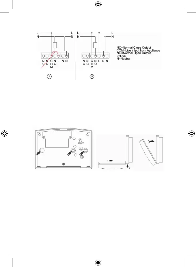
Attach the contacts as follows:
Diagram:
In case the thermostat’s source of the power is the same as well as for the attached device, connect according to the
Diagram a). Do not remove the pre-installed wire bridge between the COM contact and L contact!
Connect the phase conductor into the COM terminal.
In case the thermostat’s source of the power is NOT the same, connect according to the Diagram b).
However, before, remove the pre-installed wire bridge between the COM contact and L contact!
Finish the installation of the switching unit by mounting it with the help of 2 enclosed screws. Before screwing the
contacts’ cover do not forget to synchronize the control and switching units, see the chapter: Radio Signal Address
Setting.
Put the front cover back.
Radio Signal Address Setting
The radio signal address enables the information transfer between the control and switching unit. There may be other
dierent devices operating on the same or similar frequency and they may cause the connection interference or other
complications. To avoid such complications it is necessary to use the adequate radio code. For the code setting there
are determined 4 switches of a DIP type, placed inside of the both units.
1. Before you start to modify the address code, take out the batteries and unplug the main electric cable!
2. Withdraw the back cover from the control unit – there are 4 DIP switches on the printed circuit board.
3. Set the address code by moving some switches into the ON position and write down their status.
4. Set the same code on the switches which are placed in the switching unit. The transmitter’s address code must be
the same as the receiver’s address code.
DIP switches for the address code setting – marked with the arrow