3
GB | Capillary Sensor Thermostat
Properties
• capillary sensor thermostat (0.9 m, Ø 6 mm)
• 5 °C – 90 °C temperature range (0.1 °C resolution)
• simple electrical connection via screwless terminals
Specications
Switched load: max. 230 V AC; 5 A for resistive load; 1.5 A for inductive load
Power supply: 230 V AC
Temperature control range: 5 °C – 90 °C
Temperature measurement: 5 °C to 90 °C with 0.1 °C resolution; accuracy ±1.5 °C
Temperature setting: 5 °C to 90 °C in 0.1 °C increments
Hysteresis setting: 0.1 to 15 °C with 0.1 °C resolution
Enclosure: IP40
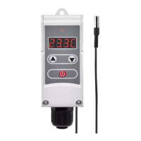
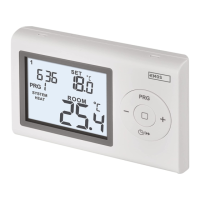
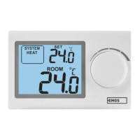
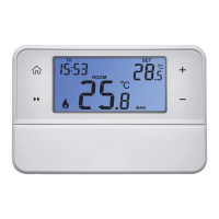
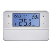
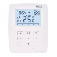
Thermostat Description
(see Fig. 1)
1 – activation indicator LED
2 – display
3 – up arrow (increase value)
4 – down arrow (decrease value)
5 – on/o/function setting button
6 – screws
7 – capillary sensor
Installation
Mount the thermostat onto any section of the pipe and secure the external sensor onto the surface
of the water delivery system the sensor is to measure. Make sure the sensor is in direct and safe
contact with the surface. (Before securing the sensor, it is necessary to remove all insulation from
the spot where it will be installed.)
Electrical Connection
1. Remove the 2 screws on the front housing of the thermostat.
2. Carefully remove the front housing.
3. Connect in accordance with the following diagram (see Fig. 2):
Pump
Power – 230 V
Jump – jumper
PE – protective earth, prevents injury by electrical current
4. The thermostat features a screwless conductor connection. Press downwards onto the top plastic
connector with e.g. a screwdriver. The terminal contact will release. Plug in the conductor. Repeat
the process for all conductors needed for connection. Replace the screws.
The device may only be installed by a professional plumber in accordance with the connection
diagram. In addition, the connection must meet up-to-date, valid VDE standards and specications
of your energy provider. Installation must always be performed when power is turned o; follow
safety specications. Maintain the maximum switched load listed in technical specications! The
manufacturer is not liable for inexpert installation.
Putting the Device into Operation
Connect the thermostat with pump according to instructions.
Connect the thermostat to 230 V power supply.
Short-press the
button.
The currently set mode and heating/cooling mode setting will ash on the display (e.g.: F1/C1).
Then, the current temperature will be displayed.