9
MAINTENANCE OF POPPET
- Usea3/32”hexwrenchandinsertitintothebackoftheBoltGuideCap.Turncounter-clockwise
untilBoltGuideCapiscompletelyremoved.(Fig7-5)
- InspectandlubricateBoltGuideCapO-ring.
- Carefullyinsertanon-metallicobject(likethebackofapen)intothefrontoftheBoltGuide.Push
PoppetAssemblyoutthebackoftheBoltGuide.(SpringmayfalloutofBoltGuide)(Fig7-6)
- LubricatethePoppetO-ring,whichisthemostimportantO-ringusedintheAXEandshouldbe
maintained often.
REPLACING THE POPPET SEAL
Ifthereisaslightairleakevidentcomingthroughtheboltarea,thePoppetSealmaybewornand
needtobereplaced.WiththePoppetremoved,grabthePoppetSealwithpliersandunscrewthe
PoppetbyhandfromthePoppetSeal.DonotgrabthePoppetwithpliersorputinaviceasitmay
damagethebrass.InstallthenewPoppetSealbyhand.Oncetightenedbyhand,thePoppetwillhold
thePoppetSealinplaceanditshouldnotcomeapartduringoperation.
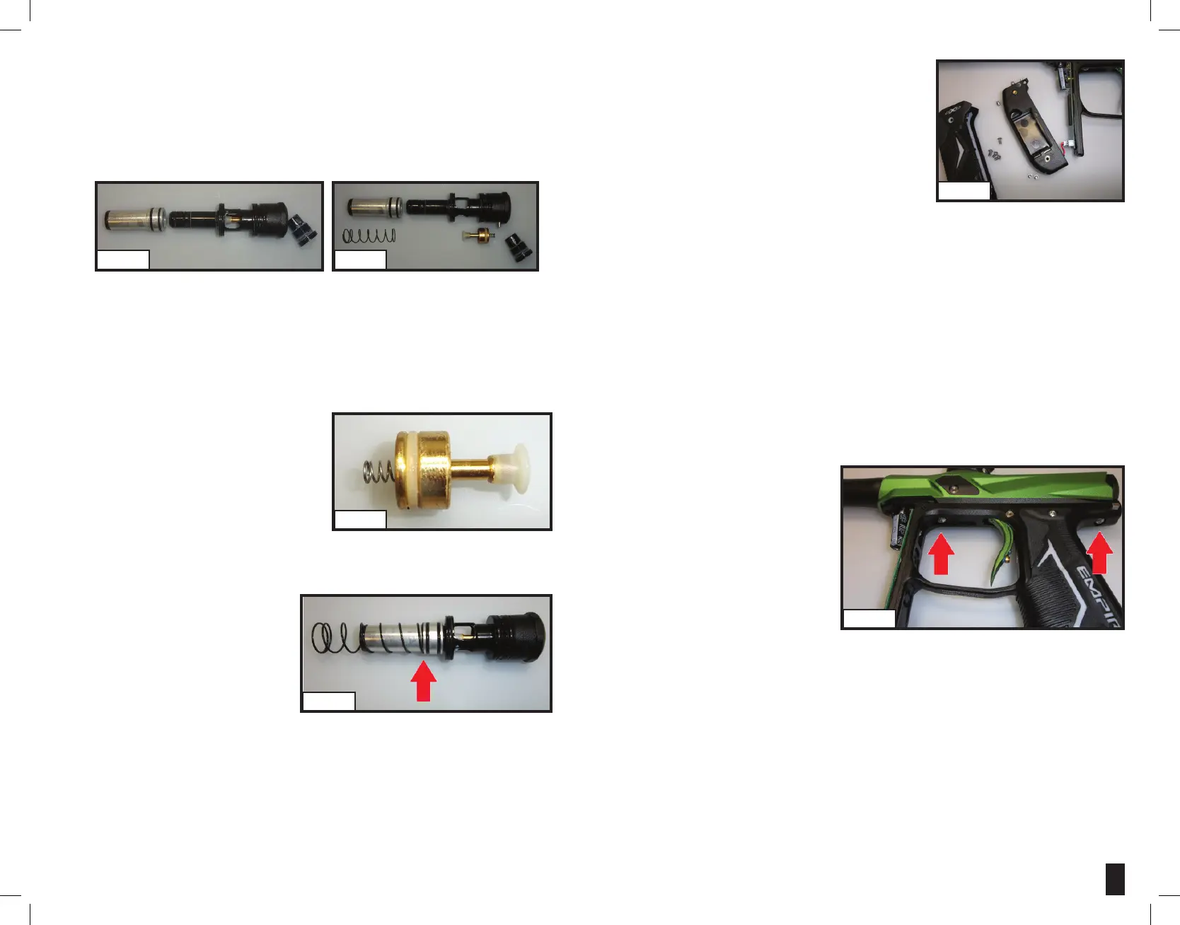
REINSTALLATION OF POPPET, POPPET SPRING AND BOLT GUIDE CAP
- PlacePoppetassemblyintothebackoftheBolt
Guideandgentlypushforward.Ifinstalled
properlythePoppetassemblywillbealltheway
forwardrestingontheBoltGuideinternalface.
MakesurethePoppetspringisseatedstraightin
thebackofthePoppet.(Fig7-7)
- Usingthe3/32”hexwrench,screwtheBoltGuide
CapclockwisebackintotheBoltGuide.Screw
theBoltguidecapallthewayin,thenturnout
1/2turn.Furtheradjustmentoverachronographwillbeneededtoachievedesiredvelocity.
REINSTALLATION OF MAIN SPRING, BOLT AND BOLT GUIDE ASSEMBLY
Slide main spring onto bolt, and then bolt onto
BoltGuide,soitisoneassembly.Youwill
notice, one end of the spring is smaller and
willlockontothebolt.(Fig7-8)Insertassembly
intothebackofBody.
Notes:
- On the bottom side of the Bolt Guide there is a small alignment pin at the rear of Bolt Guide. This must line up with the alignment hole.
- Holding the bolt assembly tight into the back of the Body with one hand, re-install the rear frame screw and tighten using the 1/8” hex wrench.
REMOVAL OF FOREGRIP ASSEMBLY
Note: Be careful with the Battery wires when removing the Foregrip.
- Usinga5/64”hexwrench,loosenandremovethefourscrewsholdingtherubberGripontotheForegrip.
- TherearevescrewsthatholdtheForegriptotheGripFrameandTransferPlate.
- Locate the two screws near the corners of the Trigger
Guard,oneoneachsideoftheAXE.Usea5/64”hex
wrench to remove those screws.
- There are three screws located on the front of the
Foregrip. One in the center at the very top and two at the
bottom.Removethemusinga3/32”hexwrench
- CarefullyunplugtheBatteryHarnessfromtheboard.Do
not pull the wires or they may break off the battery contacts.
- TheForegripassemblywillnowliftfreeoftheGrip
Frame.(Fig7-9)
INSTALLATION OF FOREGRIP
ToreinstalltheForegripAssemblyontotheGripFrameandBody.
- ConnecttheBatteryHarnessfromtheForegripintotheBoardontheGripFrame.
- SlidetheForegripassemblybackovertheboardandontotheGripFrame,aligningthescrewholes.
- Installthethreefrontscrewsusingthe3/32”hexwrenchandthetwosidescrewsusingthe5/64”
hex wrench.
- ReinstalltherubberGripusingthefourscrewsanda5/64”hexwrench.
Note: If not installed correctly, you might damage the Circuit Board!
REMOVAL OF GRIP FRAME
- Usinga5/64”hexwrench,loosenandremovethefourscrewsholdingtherubberGripontothe
Foregrip.
- PeelbacktherubberForegripandremovethetopscrewatthefrontoftheForegripusinga3/32”
hex wrench.
- Usinga3/32”hexwrench,removethetwoGripFramescrewsbyturningcounter-clockwise.(Fig7-10)
- TheforwardGripFramescrewis
locatedwithintheTriggerGuard
- The rearward screw is located at the
backofthemarker,belowtheBolt
Guide
- GentlypulldowntheframefromBody.
INSTALLATION OF GRIP FRAME
- InspecttheAirTransferTubeO-ringandlightlygrease.AsyouinstalltheGripFrame,makesure
the Solenoid wires do not get pinched and hold the Trigger in to prevent the Trigger activation lever
fromgettingdamaged.GentlypushGripFramebackonandlineuptheairtransfertubes.
- WhentheGripFrameisbackon,usethe3/32”hexwrenchandtightenthe(2)GripFramescrews
clockwise.
- Do not over tighten.
(FIG. 7-8)
(FIG. 7-9)
(FIG. 7-5)
(FIG. 7-7)
(FIG. 7-6)
(FIG. 7-10)
 Loading...