5 Operating Instructions
5.1 Connection Scheme
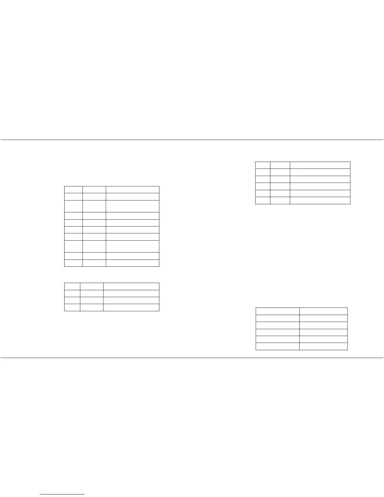
SBR-FX/RMD includes a CAN segment which
can be connected by a plug of type D-Sub9.
Pin Name Function
1 – Reserved
2 CAN_L CAN_L signal line
(dominant low)
3 GND Ground
4 – Reserved
5 SHLD Shield
6 – Reserved
7 CAN_H CAN_H signal line
(dominant high)
8 VCC Output 5V (max. 150mA)
9 – Reserved
The device is supplied via a terminal block.
Pin 1 VCC Supply 24V
Pin 2 VCC Supply 24V
Pin 3 GND Ground
Pin 4 GND Ground
SBR-FX/RMD User Manual
EMS Dr. Thomas Wünsche 13
A serial connector of the type D-Sub9 allows
the configuration of SBR-FX/RMD.
Pin Name Function
2 RXD Receiving data line
3 TXD Sending data line
4 DTR (Currently not supported)
5 GND Ground
6 DSR (Currently not supported)
The optical connection is realized by a pair of
single mode fibers (9/125µm diameter) con-
nected via LC terminals.
5.2 Router Correction Time and Cascading
The values listed below are typical values and
should fit most system configurations. The va-
lues to be used in a specific system may vary
based on parameters like busload and num-
bers of nodes. The use of a router may require
higher values for the Event Timeout settings.
If cascading is used, the Correction Time will
increase by the values of the following table
for each additional segment.
Baudrate Correction Time
20 kb/s 25 ms
50 kb/s 11 ms
125 kb/s 5 ms
250 kb/s 5 ms
500 kb/s 5 ms
User Manual SBR-FX/RMD
14 EMS Dr. Thomas Wünsche
 Loading...