Do you have a question about the EMTEST UCS 500Nx Series and is the answer not in the manual?
Details various UCS models and their configurations, including voltage and current capabilities.
Lists the international standards that the UCS N Series equipment complies with.
Explains the importance of protective earth connection for user and equipment safety.
Discusses fault current protection relays and methods to avoid nuisance tripping.
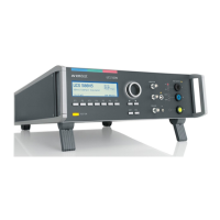
Describes the front panel controls, display, and function keys of the UCS 500N.
Details the rear panel connectors, inputs, and outputs for power and synchronization.
Explains the menu system, function keys, navigation, and parameter adjustment.
Outlines the hierarchical structure of the UCS 500N's menu system across different levels.
Details the primary menu options for selecting test types like Burst, Surge, and Power Fail.
Covers service routines, addresses, setup procedures, and status information.
Provides information on equipment status, firmware version, and operating time.
Allows selection between German and English language options for the interface.
Explains how to control the display's backlight and the Auto Off function.
Defines the status and configuration of serial and parallel interfaces.
Configures audible beeps for keyboard input and test events.
Displays equipment operating time and total test duration.
Configures output voltage levels and external source control.
Allows adjustment of factors for magnetic field testing calibration.
Step-by-step guide for setting voltage using the variac.
Details the UCS 500 N5 model, its modules, and internal structure.
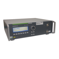
Details the UCS 500 N7 model, its modules, and internal structure.
Provides detailed technical specifications for EFT Burst tests.
Lists technical data for Surge Immunity tests according to IEC 61000-4-5.
Details specifications for Power Fail tests per IEC 61000-4-11.
Provides technical data for Ringwave Immunity tests.
Technical data for the Telecom Surge module, including pulse shapes.
Specifies the voltage and current requirements for the EUT connection.
Covers mains supply, power consumption, interfaces, dimensions, and weight.
Lists operating temperature, humidity, and atmospheric pressure requirements.
Highlights technical data for specific UCS 500Nx generator models.
Technical data for the UCS 500N5.2T special model.
Technical data for railway-specific models UCS 500N5.5, .6, and .9.
Technical data for the UCS 500N5.11 special model.
Technical data for the UCS 500N6.5 special model.
Technical data for the UCS 500N6.7 special model.
Technical data for the UCS 500N7.1 special model.
Technical data for the UCS 500N7.4 special model.
States the generator is maintenance-free due to its solid-state design.
Describes general test setup recommendations for safety and connectivity.
Explains the need for external EUT fuses and their design considerations.
Recommends transformer power rating for EUT power supply connection.
Covers factory calibration, intervals, and in-house verification procedures.
Lists the standard components included in the basic delivery package.
Details available accessories and optional modules for the UCS 500N.
Explains the operation and available test routines within the Burst menu.
Provides a quick and easy method for operating the Burst function.
Describes the selection of preprogrammed standard test routines.
Allows users to program, save, and recall custom test routines.
Details test levels and limits based on coupling configurations.
Explains the function and types of coupling/decoupling networks.
Guides on setting up tests using a capacitive coupling clamp.
Explains the operation and available test routines within the Surge menu.
Provides a quick and easy method for operating the Surge function.
Describes the selection of preprogrammed standard test routines.
Allows users to program, save, and recall custom test routines.
Allows changing polarity after a specified number of pulses.
Modifies test voltage levels based on pulse count and step value.
Adjusts phase angle based on pulse count and step value.
Automatically changes IEC coupling mode after a set number of pulses.
Changes ANSI A coupling mode based on pulse count.
Changes ANSI B coupling mode based on pulse count.
Explains phase synchronization procedures for 3-phase system testing.
Details the procedure and setup for pulsed magnetic field testing.
Configures the current limiter to protect the EUT from excessive surge current.
Shows minimal charging times for surge generator capacitors at different voltages.
Describes coupling methods for I/O lines using special networks.
Details the necessary connections for voltage dips and interruption tests.
Explains the operation and test routines within the Power Fail menu.
Provides a quick and easy method for operating the Power Fail function.
Describes the selection of preprogrammed standard test routines for voltage dips.
Covers voltage variation tests, their parameters, and simulation of motor start dips.
Details test routines for DC power supply mains according to IEC 61000-4-29.
Explains generic test routines for EN 61000-6-1 and -2 standards.
Allows manual adjustment of parameters during testing for flexibility.
Discusses operating considerations and grounding for DC power supply systems.
Details the V4780 transformer used for generating voltage dips.
Lists different models of the V4780 transformer and their specifications.
Explains how to control the V4780 S2 transformer using analog voltage.
Details the MV 2616 motor variac for voltage variations and dip simulation.
Describes the standard operating procedure for magnetic field testing.
Explains the operation and available test routines for ring wave testing.
Provides a quick and easy method for operating the Ringwave function.
Explains the coupling network used for ring wave pulse coupling.
Guides on setting up ring wave immunity tests and safety precautions.
Details the UCS 500N5T with its integrated Telecom Surge module.
Describes the external TSurge7 module for the UCS 500N7.
Navigates the TSurge module's menu and quick start test routines.
Explains the coupling network used for Telecom surge pulses.
Outlines the physical setup and cabling for TSurge module testing.
Defines voltage and current front times and decay times for surge pulses.
Provides verification data for the 10/700µs pulse waveform.
Provides verification data for the 9/720µs pulse waveform.
Documents the product's compliance with CE directives and relevant standards.
CE conformity declaration for the UCS 500N5 model.
CE conformity declaration for the UCS 500N7 model.
CE conformity for UCS 500N5x models concerning single phenomena.
CE conformity declaration for various UCS 500N5x models.
CE conformity declaration for the TSurge 7 Module.
CE conformity declaration for the CNT 516 coupling network.
CE conformity declaration for the Tapped Transformer accessory.
Provides a general block diagram illustrating the UCS 500N's architecture.
Shows the main control connections and signal flow within the UCS 500N.
Illustrates the high voltage connections and signal paths within the UCS 500N.
Explains the USB interface setup, usage, and potential interference mitigation.
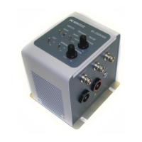
Describes the controls and connectors on the CNT 508N coupling network.
Lists the technical specifications for the CNT 508N coupling network.
Describes the controls and connectors on the CNT 516 coupling network.
Lists the technical specifications for the CNT 516 coupling network.