Do you have a question about the EMTEST CWS 500N1.3 and is the answer not in the manual?
Tests performed with RF-disturbances, induced by radio-frequency fields, are immunity tests on electronic equipment. Therefore, it is the responsibility of the user to avoid critical failures and risks to the environment and the operators.
For a test setup as per IEC 61000-4-6, the following safety aspects have to consider strictly:
EM TEST tests the instrument before shipment and pack carefully on a transport palette. Each box is marked with a detailed list of the contents.
Lists and describes the various components and their functions included with the simulator.
Detailed description of the front panel controls, display, and indicators of the CWS 500N1.x.
Detailed description of the rear panel connectors and controls of the CWS 500N1.x.
Overview of the simulator's menu control system and basic interaction methods using function keys and the knob.
Defines parameters like Voltage (V), Modulation (Mod), Frequency (f), Dwell time (td), and Calibration (CAL/CP).
Explains selectable modulation types for the signal, including 80% AM at 2Hz, 400Hz, and 1000Hz.
Provides easy and fast operation of standard functions with individual parameter settings.
Allows users to change, save, and recall specific test routines based on IEC 61000-4-6.
Changes the test level from V1 to V2, then by AV until V2 is reached, considering dwell and pause times.
Changes the test frequency from f1 to f2, then by Af until f2 is reached, considering dwell and pause times.
Changes the dwell time from td1 to td2, then by Atd until td2 is reached, considering dwell and pause times.
Lists and allows selection of preprogrammed test levels and parameters for IEC 61000-4-6 standards.
Accesses menus for calibration and amplifier saturation checks, managing calibration stores.
Guides the user through selecting and performing calibration, including overwriting existing calibration data.
Checks the generator's signal level against a calibrated signal, increasing it by +5.1dB for verification.
Displays contact addresses for EM TEST (Switzerland) GmbH and EM TEST GmbH in Germany.
Explains the setup procedure for configuring the CWS 500N1.x.
Allows users to adjust standard test levels or parameters according to preferences.
Checks the correct function of the MONITOR input and FWD/REV power inputs for the PM 1000.
Indicates the status of the TEST ON button, safety circuit, amplifier power, and temperature.
Defines settings for language, LCD backlight, interfaces, keyboard beeper, and power-on counter.
Procedure to check the simulator's performance and accuracy using an oscilloscope and specific parameters.
Checks the PM 1000 measuring input by comparing two inputs with different measurements.
Details the calibration setup for Coupling/Decoupling Networks (CDN) according to IEC 61000-4-6 Ed. 3.
Describes the calibration setup for Ed. 4, using a dual directional coupler for forward power control.
Details calibration and test setups for EM Clamps and Bulk Current Injection (BCI) clamps.
Describes Ed. 4 calibration setup for EM Clamp/BCI using generator level control.
Explains the use of the high-frequency powermeter for calibration and management of calibration files.
Details the reference plane dimensions for the 150Ω to 50Ω adaptor as per IEC 61000-4-6 Ed. 4.
Illustrates the general calibration setup for CDN, including connection to the ground reference plane.
Describes the calibration setup for an EM Clamp, noting its similarity to CDN calibration.
Details the calibration setup for a Bulk Current Injection (BCI) clamp, emphasizing cable requirements.
Provides important information for a correct test setup using Coupling/Decoupling Networks (CDN).
Details test setup configurations for EM and BCI injection clamps, including impedance and decoupling requirements.
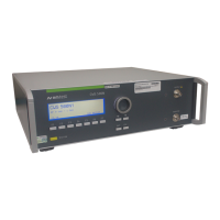
Details the internal design of the CWS 500N1.3, divided into Control, Generator, and RF Power units.
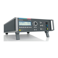
Details the internal design of the CWS 500N1.4, divided into Control, Generator, and RF Power units.
Describes the control section, including the processing unit and driver electronics.
Explains the generator unit's role in providing RF signals for amplifier operation.
Details the RF power unit, a Class A amplifier with 80 watts output and forced air cooling.
Explains the function of Fail 1 (stop test) and Fail 2 (store data, continue test) inputs and their modes of operation.
Describes the connection and purpose of the 6dB attenuator for output matching and system impedance.
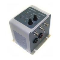
Explains the function of CDNs in coupling interference to the equipment under test and their bandwidth requirements.
Lists output level, power, impedance, VSWR, and harmonic distortion for the CWS 500N1.3.
Specifies the sinusoidal test frequencies for CWS 500N1.3 and CWS 500N1.4.
Details the amplitude and pulse modulation methods supported by the simulator.
Lists the available serial and parallel IEEE 488 GPIB interfaces and their selectability.
Provides specifications for the PM 1000 power meter, including frequency range and input range.
Lists specifications for the dual directional coupler, including frequency range and insertion loss.
Details the Class A RF amplifier specifications for CWS 500N1.3 and CWS 500N1.4.
States that the generator is maintenance-free, uses forced air cooling, and advises not to cover cooling slots.
Covers factory calibration, guidelines for determining calibration periods, and in-house verification.
Lists the standard components included with the CWS 500N1.3 or CWS 500N1.4.
Lists optional accessories such as Coupling Networks (CDN), Coupling clamps, and calibration adapters.
Declares conformity with applicable CE directives and relevant EC standards for the product.
Illustrates the overall system architecture and signal flow of the CWS 500N1.x simulator.
| Category | Switch |
|---|---|
| Model | CWS 500N1.3 |
| Switching Time | 10 ms max |
| Impedance | 50 Ohm |
| Connector Type | N-Type |