Fail 1: A short circuit at the Fail 1 input will stop the test procedure. It is not possible to
continue this test.
Fail 2: A short circuit at the Fail 2 input will store the actual test data. The test procedure
will continue normally.
The display indicates the number of Fail 2 events.
After the first Fail 2, the following events on the same test level are ignored (for the
actual selected dwell time).
When the counter detects 10 Fail 2 events, the test will stop automatically. After a
new start the counter will be reset to zero.
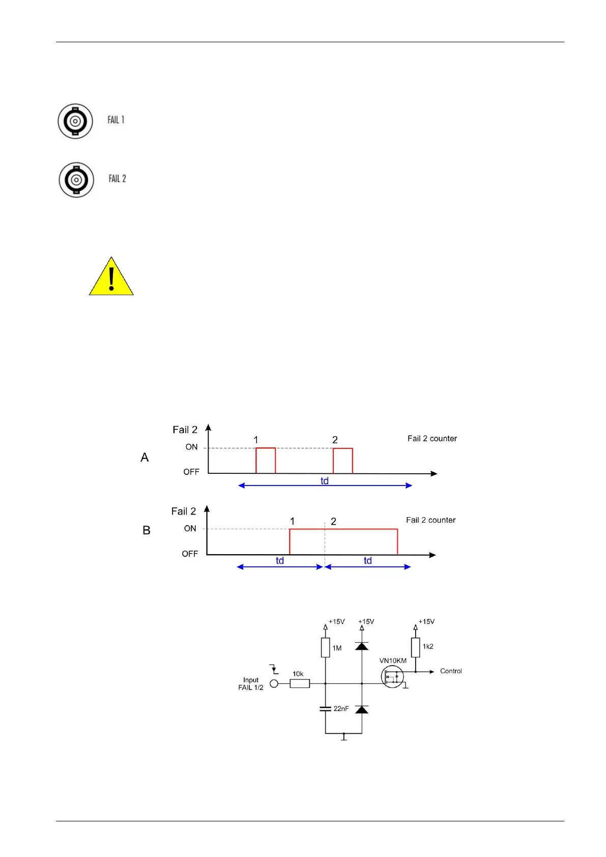
Mode of operation for Fail 2 (figure 8.3 )
The Fail 2 will increase the counter each event during the dwell time td with the following
mode:
A: Single Events during td
Each Fail 2 event will increase the counter.
No function until the counter has reached 10 counts and the test stops.
B: Fail signal is present during longer time
If the Fail 2 signal is present during longer time; the Fail 2 counter will increase
exact one-step as during the dwell time td. Beginning with the next step, the Fail 2
counter will increase for the new dwell time. The test will stop after the counter
reached 10 events.
Fail function: Input signal: Negative slope.
NOTE: The signal is release to high before you start the next test.
Figure 8.4 Fail 1/2 input circuit diagram