10 11
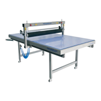
9. Remove all the wrapping from the beam.
(Take care not to damage the roller.)
11. Adjust the distance from the Glide beam’s legs to the table side according to the written measurement. 12. Put the Glide beam to the short side and lower
the roller. NOTE: Don’t raise the roller until steps
13-19 are done.
13. Place the Aluminum prole against the roller. Point out the distance from the prole to the end of the table (see
the blue circle). Make sure the distance is equal (+/- 1 mm. ) on both sides, otherwise release the pressure and
change the position of the Glide beam (shake the roller back and forth to change it’s position), repeat the procedure
until the measurement is the same on both sides.
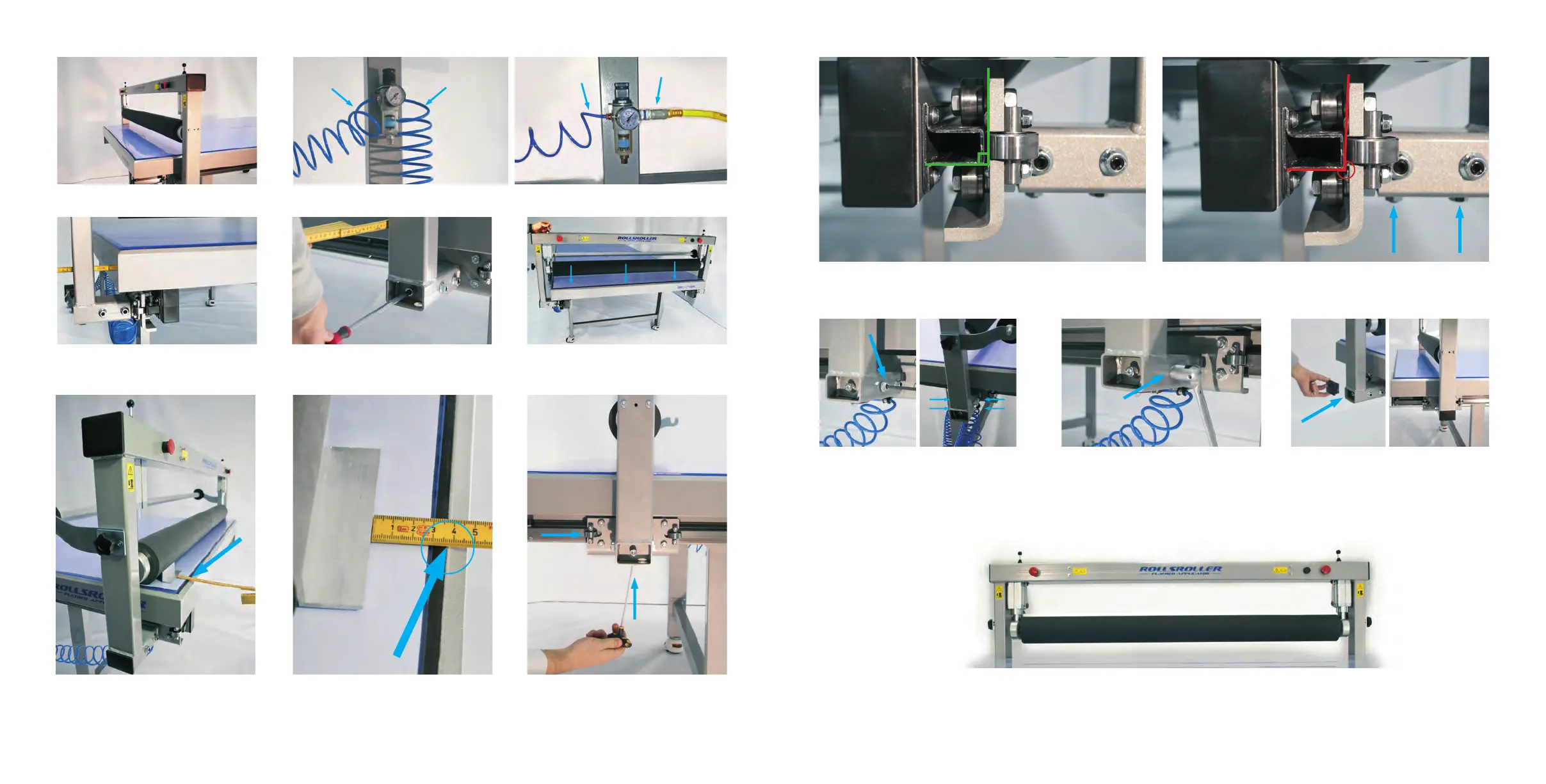
14. Adjust the angle of the bearings with the screws
underneath the glide feet so they align with the
glide rail (see pictures 15-16).
10. Connect the Glide beam air hose to the regulator (hose A). If using a ROLLSROLLER compressor connect air
hose B to the regulator. If using an external air system, connect hose C to the regulator.
A B
A C
17. First, lightly tighten the horizontal clamping
screws. Then use the allen key to tighten the screws
in the following pattern A, B, C, D (se right picture
above). Follow this pattern until the clamping screws
are secured properly.
19. Attach the Glide beams end covers on both
sides.
18. Lock all six clamping screws.
20. Raise the roller and the Glide beam is now installed.
15. This image shows the correct angle of the bearing (approximately 90°). 16. If the bearings do not align with the glide rail (see picture above),
adjust the lower clamping screws until the angle is correct (picture 15).
C
A
D
B