Thank you for choosing ENDA EI2041 INDICATOR.
TECHNICAL SPECIFICATIONS
HOUSING
Housing type
Suitable for flush-panel mounting according to DIN 43 700.
Dimentions
W77xH35xD71mm.
Weight
Approx. 350g (after packaging)
Enclosure material
Self extinguishing plastics.
While cleaning the device, solvents (thinner, gasoline, acid etc.) or corrosive materials must not be used.
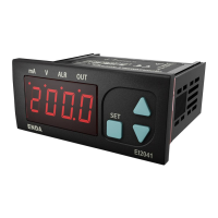
ENDA EI2041 PROGRAMMABLE INDICATOR
OUTPUTS
Sensor power supply
All sensor supply outputs maximum 50 mA. (Regulated and isolated).
Out
Relay: 250V AC, 8A (for resistive load), NO; 1/2 HP 240V AC CosF = 0.4 (for inductive load).
Alarm
Relay: 250V AC, 8A (for resistive load), NO; 1/2 HP 240V AC CosF = 0.4 (for inductive load).
Life expectancy for relay
Mechanical 30.000.000 operation; 100.000 operation at 250V AC, 8A resistive load.
CONTROL
Control type
Double set-point and alarm control.
Control algorithm
On-Off control.
Hysteresis
Adjustable between 1 ... 200.
ENVIRONMENTAL CONDITIONS
Height
Max. 2000m.
Ambient/storage temperature
Max. relative humidity
0 ... +50 °C/-25 ... +70°C (with no icing).
Rated pollution degree
80% Relative humidity for temperatures up to 31°C, decreasing linearly to 50% at 40°C.
According to EN 60529 Front panel : IP65 Rear panel : IP20
Do not use the device in locations subject to corrosive and flammable gases.
EI2041 cannot be used if measurement category II, III or IV is required.
Supply
230V AC 110V AC +%10 -%20 , 12/24V AC ±%10, 50/60Hz or 9-30V DC /7-24V AC ±%10 SMPS optional.
Power consumption
Max. 7VA.
2.5mm² screw-terminal connections.
Wiring
Date retention
EMC
Safety requirements
EN 61326-1: 2013.
EEPROM (Min. 10 years).
EN 61010-1: 2010 (Pollution degree 2, overvoltage category II, measurement category I).
ELECTRICAL CHARACTERISTICS
Input type
0-1V DC voltage
0-10V DC voltage
0-20mA DC current
4-20mA DC current
Input empedance
Approx. 100kW
Approx. 100kW
Approx. 10W
Approx. 10W
0V
±0,5% (of full scale)
0V
±0,5% (of full scale)
0mA
±0,5% (of full scale)
0mA
±0,5% (of full scale)
1.1V
12V
25mA
25mA
Min.
Max.
Measurement range
Measurement accuracy
While the current measuring mode, input impedance becomes 10Ω . Therefore, in current mode, the device must not be connected any voltage input.
Otherwise, the device is broken. While the device is running in the voltage measurement mode and if required to change to current measurement mode, then
firstly the voltage inputs must be removed and after that, input type must be changed to one of the current measurement modes.
SİSEL MÜHENDİSLİK ELEKTRONİK SAN. VE TİC. A.Ş.
Şerifali Mah. Y.Dudullu 34775
ÜMRANİYE/İSTANBUL-TURKEY
Tel : +90 216 499 46 64 Pbx. Fax : +90 216 365 74 01
url : www.enda.com.tr
Barbaros Cad. No:18
EI2041-EN-01-180411
1/5
ENDA
TM
Read this document carefully before using this device. The guarantee will be expired by device demages if you don't attend to the
directions in the user manual. Also we don't accept any compensations for personal injury, material damage or capital
35x77mm sized.
4 digits display.
Display scale can be adjusted between -1999 and 4000.
Decimal point can be adjusted between 1st. and 3rd. digits.
Measurement unit can be displayed.
Selectable four different standard input types (0-20mA, 4-20mA, 0-1V, 0-10V).
User can calibrate the device according to specified input type.
Sampling time can be adjusted in four steps.
Stores maximum and minimum measurement values.
Maximum and minimum values can be stored and displayed.
Two relay output for control and alarm (Optional).
Control option below and above set value.
Selectable independent, deviation and band alarm.
Sensor supply output (Optional).
RS485 Modbus RTU communication protocol feature (Optional).
CE marked according to European standards.
Order Code : EI2041
1
1 -
Supply Voltage
230...........230V AC
110............110V AC
024.............24V AC
012.............12V AC
SM..........9-30V DC /
7-24V AC
2 3
2 -
Blank or XX....N/A
2R.......OUT and ALARM
Relay Output
3 -
Blank or XX....N/A
24....24V DC 50mA
12....12V DC 50mA
08......8V DC 50mA
05......5V DC 50mA
Sensor Supply
4 -
Blank or XX....N/A
RS....
Modbus
Modbus Communication
4
Please specify all
features carefully
EI2041
mA
V
ALR
OUT