Fastlane
®
Swim Unit Installation Fastlane
®
Swim Unit Installation
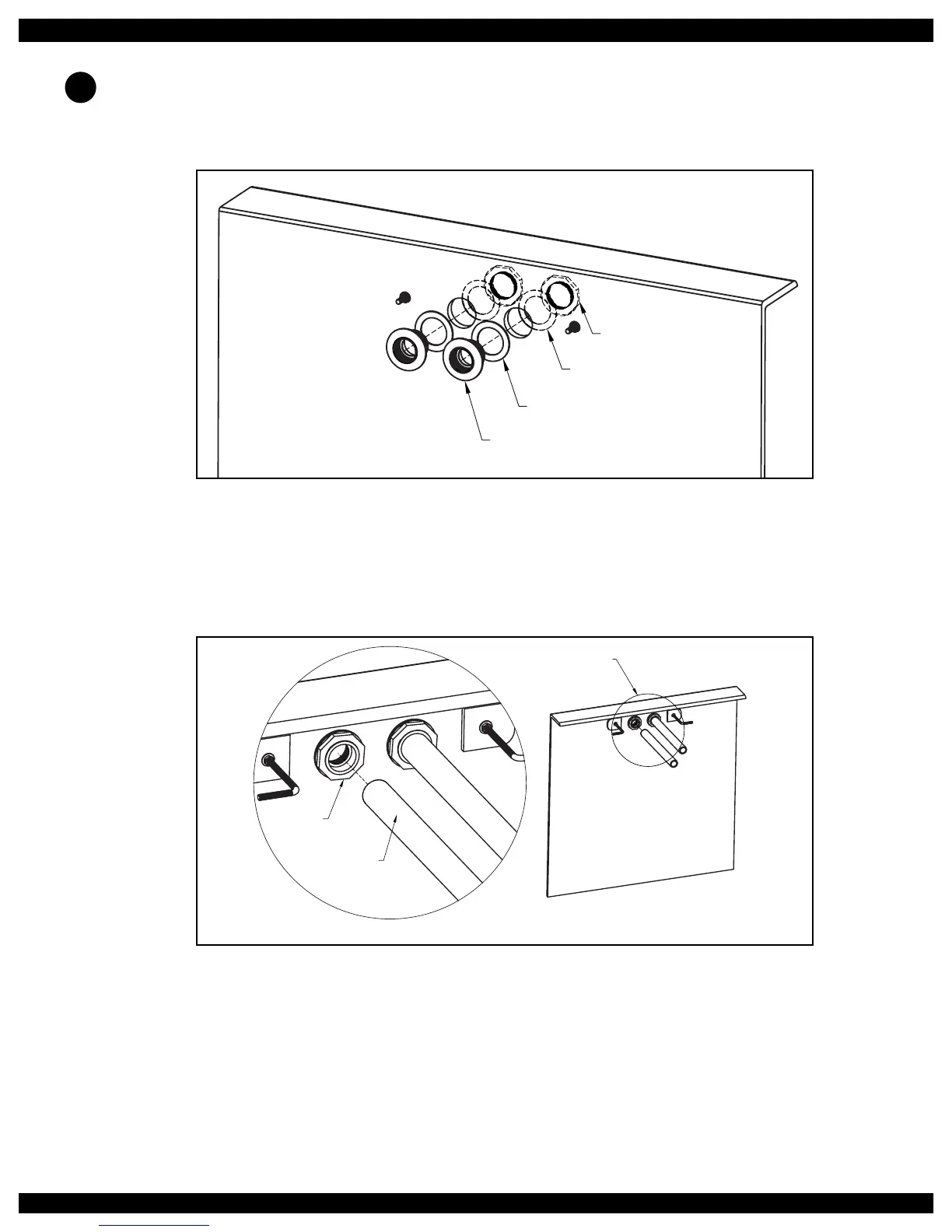
The backside of the thru-wall holes may need to be sanded at so that a proper seal can be made. Place one
of the rubber gaskets onto each thru-wall tting. The second rubber gasket will not be used in this applica-
tion. Insert the thru-wall ttings into the cut outs and place the cork gaskets onto the ttings on the backside
of the pool wall. Thread the lock nuts onto the ttings. The lock nuts should be tightened with a pair of
channel locks or strap wrench (Fig 4.27).
Thru-W
all
Fi
tting
Rubber
Ga
sket
Lo
ck Nu
t
Cork
Ga
sket
Fig. 4.27
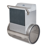
Unroll the exible PVC from the wall mount bracket back to the hydraulic power unit. Any bends in the
exible PVC should be gradual sweeps and not sharp to allow the hydraulic hoses to easily be fed through
each conduit. Each length of PVC must be no longer than 21ft (6,4m) and should exit the ground near the
hydraulic power unit. Glue the PVC ex pipe into the thru-wall ttings at the wall mount bracket (Fig
4.28).
DETAIL A
PVC Flex Pipe
(See Detail A)
Thru-Wall
Fitting
1-1/2" (38mm)
PVC Flex Pipe
Fig. 4.28
If the distance between the wall mount bracket and the hydraulic power unit is greater than 25ft (7,6m)
then a junction box and additional ex pipe must be employed. In this case, the ex pipe between the wall
mount bracket and the junction box must be 24ft 6in (7,5m). This will allow the hydraulic hoses attached to
the Fastlane to terminate just inside the junction box. See section 5 for additional information.
22
W