4
Enea
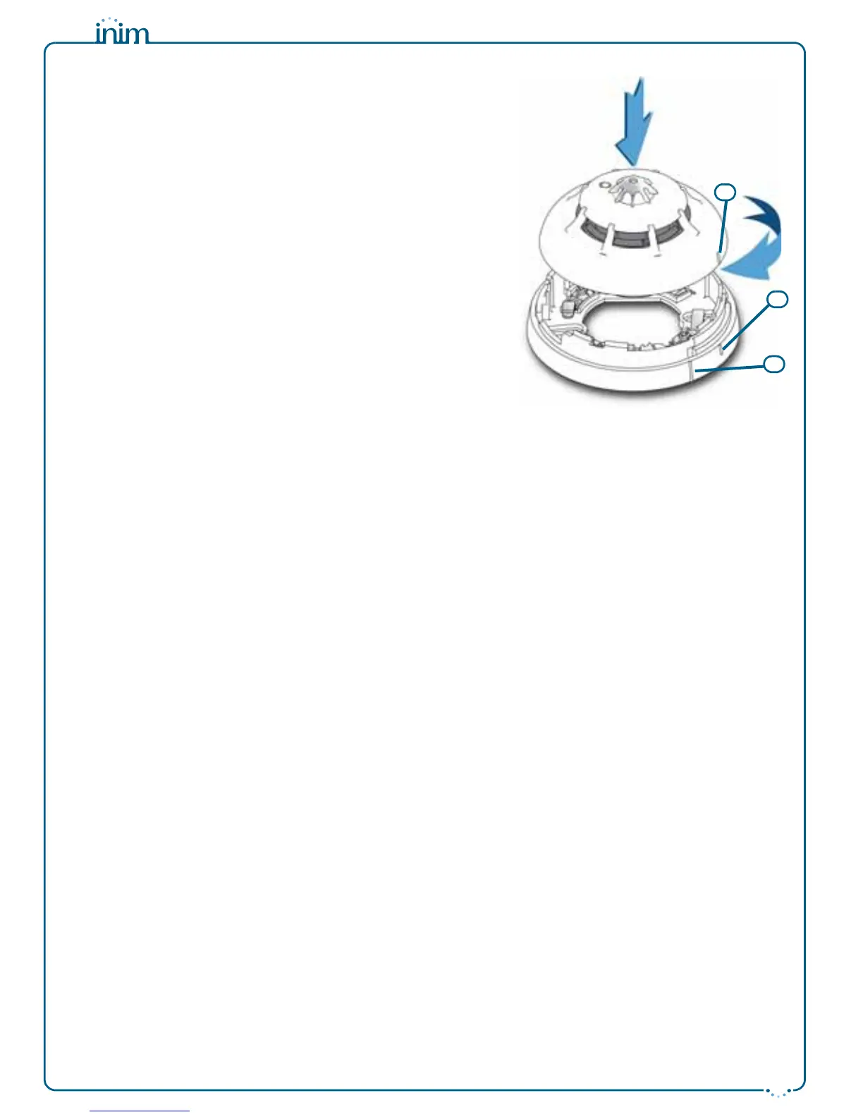
Once the base is located properly in its placement, place the detector
unit onto the base and, with minimum force, turn it clockwise until
notch “A” aligns with notch “B” (in order to attach the detector to the
base); turn it still further until notch “A” aligns with notch “C” (in
order to allow the base to engage with the detector contacts).
When installation of all the loop devices is complete, proceed with
the addressing phase. Refer to the respective section in the control
panel installation and programming manual.
Testing and maintenance
After installation and during periodic maintenance inspections, you
must carry out the following operations on each detector:
•
Check the LED
; if the yellow LED is On solid, the detector is in fault
status. The detector may simply require cleaning, however, if after
cleaning, this condition persists, you should remove the faulty detector
and replace it with a new one. The control panel will allow you to trace
and identify the cause of the fault.
•
Optical smoke detector test
; smoke detectors should be tested
immediately after installation and periodically during maintenance
inspections in accordance with the established standard regulations and
codes in force. To test smoke detectors, use an approved test aerosol
strictly in accordance with the accompanying instructions.
Ensure that the smoke inlet ports to the smoke detection chamber are not
blocked. Check the contamination level of the smoke detection chamber
via the control panel. If the contamination level is high (above 50%),
detach the detector from its mounting base, open the device and, using a
small, soft-bristle brush or hand-held vacuum cleaner remove all dust
particles from inside and around the smoke detection chamber and free
the protection net from all contaminants.
•
Heat detector test
; using a suitable device (e.g. hairdryer), create heat in the vicinity of the detector, then work through
the steps described in the device instruction sheet. During each periodic maintenance inspection, ensure that the heat
element is intact and that is not obstructed by dust or paint. If it is, using a small, soft-bristle brush or hand-held vacuum
cleaner remove all contaminants.
Operating mode
The three-colour LED (360° viewing) indicates the detector status, as follows:
• Green blinking at 15-second intervals; the detector is in standby status (i.e. operating properly).
• Green On solid; the LED has been activated manually from the control panel. This operation allows easy identification of
the detector.
• Yellow On solid; the detector is in fault status or has detected a short-circuit in the succeeding wiring section (short-circuit
isolator open). Further details regarding the fault can be obtained through the control panel.
• Red On solid; the detector is in alarm status. Further details regarding the alarm can be obtained through the control panel.
Each detector has an output (terminal “R”), for the connection of an alarm repeater LED. This LED will activate in
accordance with programming carried out via control panel. The detector is also capable of discerning whether its
repeater LED has been connected. This function provides indications (on the control panel) regarding the
detectors with connected LEDs, and also fault signals in the event of disconnection.
Using the EITK-DRV driver
The EITK-DRV driver allows you to change the operating parameters of the detectors, check the contamination
level of the smoke chambers and also obtain accurate diagnostic data. It can operate through the USB port of a
computer furnished with the relative software programme, or can function autonomously by way of the battery
housed inside.
Each detector is capable of retaining memory (smoke and/or temperature depending on the model) of the 5
minutes prior to an alarm. Therefore, if an alarm occurs, it will be possible to obtain information regarding the
onset of the fire by simply connecting the EITK-DRV driver to the detection line.
For further information and details regarding use of the EITK-DRV driver, refer to the respective handbook.
Warnings and limitations
Enea series detectors must be used exclusively with fully compliant, compatible control panels. Detectors may
not provide timely warning of fire if coverage is limited by large obstructions (pillars, large machinery, etc.).
When installing or working on a fire detection system, always refer to and comply with the established standard
regulations and codes. Appropriate fire-risk assessment should be undertaken to determine the type of detectors
required and their placements.
 Loading...