Table of Contents
INTRODUCTION............................................................................................................................................................................................................................1
MOUNTING ....................................................................................................................................................................................................................................2
INSTALLING/CHANGING BATTERIES....................................................................................................................................................................................2
Figure 1 — Battery Locations ......................................................................................................................................................................................................................... 2
Replacing same type batteries (Alkaline or Lithium).................................................................................................................................................................2
Figure 2 — Opening Thermostat..................................................................................................................................................................................................................... 2
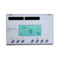
FOUR-BUTTON / HOTEL CONFIGURATION..........................................................................................................................................................................3
Figure 3 — Four-Button Cluster...................................................................................................................................................................................................................... 3
Figure 4 — Four-Button LCD Display............................................................................................................................................................................................................ 3
SEVEN-BUTTON CONFIGURATION.........................................................................................................................................................................................4
Figure 5 — Three-Button Cluster.................................................................................................................................................................................................................... 4
SETTING THE CLOCK ......................................................................................................................................................................................................................4
PROGRAMMING YOUR THERMOSTAT..................................................................................................................................................................................5
RUN BUTTON .................................................................................................................................................................................................................................6
CHANGING TEMPERTATURE WHILE RUNNING A PROGRAM.......................................................................................................................................6
IMPORTANT NOTE ..........................................................................................................................................................................................................................6
INSTALLING AND REMOVING NODES...................................................................................................................................................................................7
The Linking Procedure..............................................................................................................................................................................................................7
Installing Nodes .............................................................................................................................................................................................................................................. 7
Removing Nodes........................................................................................................................................................................................................................7
All Nodes Removal......................................................................................................................................................................................................................................... 7
Setting Min/Max Set Point.........................................................................................................................................................................................................8
Figure 7 — Internal Button ............................................................................................................................................................................................................................. 8
TROUBLESHOOTING FAQ .........................................................................................................................................................................................................9
Figure 1 — PTAC RCN Connection Diagram ..................................................................................................................................................................................... 12
Figure 2 — J-Box RCN Electric Heat Example................................................................................................................................................................................... 13
Figure 3 — J-Box RCN Fan Coil Example.......................................................................................................................................................................................... 14
Figure 4 — Plug RCN Fan Coil Example ............................................................................................................................................................................................ 15
 Loading...