2
3.0 PRODUCT DESCRIPTION
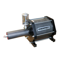
These double-acting air operated hydraulic boosters convert low
pressure air into high pressure hydraulic oil for operating cylinders,
clamps or similar devices. Main booster components are: the air
piston and the hydraulic plunger. Air pressure, into the booster, exerts
a force against the air piston causing it to move forward. The forward
motion moves the hydraulic plunger in the oil cylinder. The hydraulic
plunger compresses the oil in the cylinder developing high pressure at
the outlet port. Included with each booster is an oil reservoir.
4.0 INSTALLATION
4.1 Booster Installation
The preferred mounting position for the present model would be
vertical with the air cylinder on top. The pump outlet should be above
the system/circuit and the reservoir is always the highest point of the
oil. This will allow the bleeding to be natural to the system and no
extra work should be needed to bleed air out of the hose and pump.
Bleeding the fixture will be unique to each design. Air will rise up from
the fixture, through the hose, through the pump and into the reservoir
naturally.
IMPORTANT: When mounting the booster, the air fill cap and oil level
indicator must always remain visible and usable to permit checking
and re-filling of the reservoir.
4.2 Incoming Air Supply
Compressed air, to the booster, must be clean, dry and lubricated to
protect the booster components. If properly treated air is not
available, install an ENERPAC filter lubricator in the air line leading to
the booster control valve. The filter lubricator provides following
advantages:
1. Removes dirt and moisture from the air.
2. Provides a mist of lubrication in the air supply which protects
control valves and booster internal parts.
3. Contains an air regulator valve and gauge to adjust air pressure to
the booster.
4.3 Air and Oil Connections
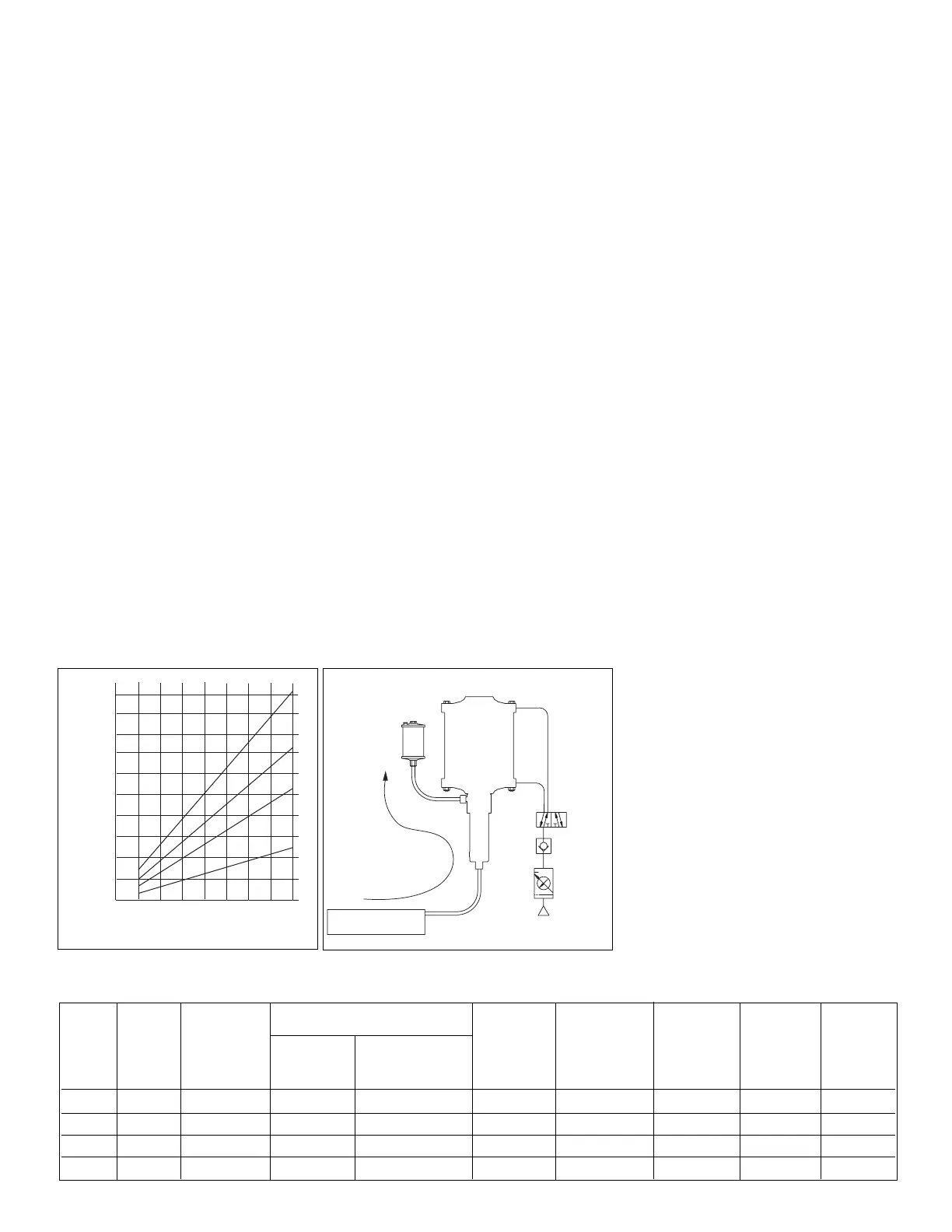
1. A 5-way, 2-position directional control valve is required to operate
this double-acting booster.
2. Connect air supply line to input port on filter lubricator unit.
3. lnstall an air supply line from filter lubricator to the valve.
4. Install air supply lines from valve to booster.
5. Attach the hydraulic lines from booster to the system working
components.
6. Mount oil reservoir. To fill booster, plunger must be in retracted
position.
7. Fill booster hydraulic reservoir with ENERPAC hydraulic oil.
5.0 BOOSTER OPERATION
Booster operating speed depends on factors including working cylinder
strokes, valving, hose lengths, port sizes and air supply flow.
1. Provide air supply of 1.4-8 bar (20-115 psi).
2. All hoses, fittings, piping and components must be pressure rated
to withstand maximum system pressure. See specification chart.
3 Maintain booster oil level in the reservoir. Check oil level indicator
frequently. Repair leaks immediately.
4. Prior to operation bleed system to remove air trapped in the
hydraulic system. Refer to §5.1.
5.1 System Bleeding
1. Check oil reservoir level in booster. Fill to capacity if needed.
2. When using a booster in a horizontal position, the booster MUST
be tilted with the air cylinder up and cycled a few times.This will
remove the air in the booster and provide better performance from
the pump. It should be noted that when the system is bled
properly that the reservoir serves as a place for a small amount of
oil to move into as the booster starts its strokes and it then
supplies that same amount of oil on the return stroke. The
reservoir also replenishes the oil lost through leakage. Note: The
system should be designed to allow the air to rise naturally
through the hydraulic system.
3. To bleed fixture, stroke booster and open
one fitting at a time to bleed air then close
fitting and retract booster. Repeat with
each fitting starting with the closest and
work to the farthest fitting. CAUTION
should be used when releasing the
hydraulic pressure to prevent injury.
4. Always keep the oil reservoir full to
capacity during bleeding and when the
system is in use.
Model Pressure Maximum Oil Pressure at Oil Volume Air Pneumatic Effective Weight
No. Ratio Air Pressure at Full Consumption Diameter Stroke
6 Bar Air Max. Air Stroke at 6 Bar
Pressure Pressure 8 Bar
bar [psi] bar [psi] bar [psi] cm
3
[in
3
]dm
3
[in
3
] mm [inch] mm [inch] kg [lbs]
AHB-17 16:1 8 [116] 96 [1390] 128 [1860] 295 [18] 62,6 [3820] 203 [8.0] 145 [5.7] 18,8 [41.4]
AHB-34 34:1 8 [116] 204 [2960] 272 [3940] 140 [8.5] 63,6 [3880] 203 [8.0] 145 [5.7] 16,9 [37.3]
AHB-46 46:1 8 [116] 276 [4000] 368 [5340] 100 [6.1] 63,9 [3900] 203 [8.0] 145 [5.7] 16,4 [36.2]
AHB-66 64:1 8 [116] 384 [5570] 512 [7420] 73 [4.5] 64,1 [3910] 203 [8.0] 145 [5.7] 16,1 [35.5]
Table I - Specifications


 To Next Page
 Loading...