This document provides a comprehensive guide for the BVS4/BVR4 Electric Valves, covering their function, technical specifications, usage, and maintenance. It includes detailed parts lists, exploded views, troubleshooting steps, and repair instructions to ensure optimal performance and longevity of the device.
Function Description
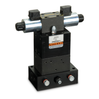
The BVS4/BVR4 Electric Valves are critical components in hydraulic systems, designed to control the flow and direction of hydraulic fluid, thereby enabling the operation of various hydraulic equipment. These valves are solenoid-operated, meaning they use an electrical current to actuate a spool, which in turn directs the hydraulic fluid. The "Advance" and "Retract" solenoids control the movement of a directional piston, allowing the valve to operate in both directions.
The valve assembly comprises several key sections:
- Solenoid Assembly: This is the electrical control unit, responsible for converting electrical signals into mechanical motion to shift the valve spool. It includes the solenoid coils, rectifier assembly, and terminal box.
- Valve Block Assembly: This is the core hydraulic component where fluid flow is managed. It houses various internal components such as pistons, springs, balls, seats, gaskets, and adjusting screws that regulate pressure and direction.
- Pilot Relief Section: This section controls the pilot pressure, which is essential for the proper functioning of the main directional piston. It includes a ball, spring, and adjusting screw to set the pilot relief pressure.
- High Pressure Relief Sections: These sections protect the hydraulic system from overpressure in both the advance and retract directions. They consist of balls, springs, ball guides, and adjusting screws to set the maximum operating pressure.
- Directional Piston Sections (Advance and Retract): These sections contain pistons, springs, balls, and seats that physically direct the hydraulic fluid to either the advance or retract port of a cylinder.
The valve's operation relies on a delicate balance of pilot pressure and the mechanical action of springs and pistons. When a solenoid is energized, it shifts a spool, which then directs pilot pressure to one side of the main directional piston, causing it to move and open/close fluid paths. This allows the hydraulic fluid to flow to the desired port, initiating either an advance or retract motion in a connected cylinder.
Important Technical Specifications
The manual provides several critical technical specifications, particularly related to pressure settings and torque values, which are vital for proper assembly, adjustment, and operation:
- Pilot Adjusting Screw Pressure: 850-900 PSI [58.7-62.1 Bar]. This setting is crucial for the responsiveness and stability of the valve's directional control.
- High Pressure Relief Setting: 11,000-11,500 PSI [759.0-793.5 Bar]. This is the maximum pressure the valve will allow in the main hydraulic circuit, protecting the system from damage due to excessive pressure.
- Pilot Relief Adjustment: 1150-1200 PSI [79.3-82.8 Bar]. This setting is for the pilot relief section, ensuring the correct pilot pressure is maintained.
- Spring Compression (Item 27): When installing a new spring (Item 27), it must be compressed to 750 PSI [51.8 Bar] (1680 lbs of force) using a 10 Ton ENERPAC press prior to assembly. This ensures the spring provides the correct resistance for the pilot piston.
- Torque Settings for Ball Seats:
- Lower seat (Item 40): 25 ft-lbs [33.9 Nm].
- Upper seats (Items 38 & 39): 37 ft-lbs [50.2 Nm].
- These torque values are critical for preventing leakage and ensuring the integrity of the ball seats, which are essential for sealing fluid paths.
- Cap Screw Torque (Item 41): 10-12 ft-lbs [13.7-16.3 Nm]. This applies to the cap screws holding the cover plate.
- Pressure Hold Test: The valve should hold pressure at 10,000 PSI [700 Bar] without leakage. During a 15-second hold, there should be less than a 300 PSI [20.7 Bar] drop, and no cylinder creep. This specification indicates the sealing efficiency and overall health of the valve.
- Output Test Pump: A 700 cu. in./min. [11,473 cu.cm/min.] output test pump is recommended for adjustments.
- Gauge Placement: A 2,000 PSI [138.0 Bar] gauge should be inserted in the 1/16" NPT port on the block nearest the cover plate for pilot relief adjustments. A 15,000 PSI [1035.0 Bar] gauge is used for advance and retract port pressure monitoring.
Usage Features
The BVS4/BVR4 Electric Valves are designed for integration into hydraulic systems requiring precise directional control.
- Solenoid Operation: The electrical solenoids allow for remote and automated control of the valve, making it suitable for various industrial applications where manual intervention is impractical or undesirable.
- Dual Directional Control: The "Advance" and "Retract" solenoids enable the valve to direct fluid in two directions, facilitating the extension and retraction of double-acting hydraulic cylinders.
- Pressure Relief: Integrated high-pressure relief sections protect the hydraulic circuit from damage due to excessive pressure, enhancing system safety and longevity.
- Pilot Control: The pilot relief section ensures stable and accurate control of the main directional piston, contributing to smooth and reliable operation.
- Modular Design: The valve's construction, with separate solenoid and valve block assemblies, facilitates easier maintenance and replacement of individual components.
- Troubleshooting Guidance: The manual provides a comprehensive troubleshooting section that helps identify common issues such as electrical malfunctions, pressure leaks, inability to build maximum pressure, and directional control problems. This guides users in diagnosing issues before attempting repairs.
Maintenance Features
The manual emphasizes several key aspects of maintenance, focusing on proper disassembly, cleaning, inspection, and reassembly to ensure the valve's optimal performance.
- Repair Kit (VS4-24K1): The document highlights that certain items (marked with ★) are included in and available only as part of the Repair Kit VS4-24K1. This indicates that specific components are considered wear items and should be replaced during routine maintenance or repair.
- Component Replacement: The repair instructions explicitly state to "INSTALL ALL KIT COMPONENTS TO INSURE OPTIMUM PERFORMANCE OF THE REPAIRED PUMP" and to "use new parts supplied in repair kit" during reassembly. This underscores the importance of replacing worn or damaged parts with new ones for reliable operation.
- Gasket and O-Ring Replacement: Used copper gaskets should be discarded and replaced with new items from the repair kit. New O-Rings and back-up washers should be installed on all three pistons. This is crucial for maintaining seals and preventing fluid leakage.
- Inspection: Before reassembly, all components should be cleaned and inspected for wear or damage, particularly ball seats, springs, and relief ball seats. This proactive inspection helps identify potential failure points.
- Ball Seat Seating: If new seats are used, they must be seated by placing the ball on the seat and pressing to 200 PSI [13.8 Bar] on a 10-ton press. This ensures proper sealing and prevents leakage.
- Spring Compression: As mentioned in technical specifications, the main spring (Item 27) requires pre-compression to 750 PSI [51.8 Bar] before assembly, which is a critical maintenance step.
- Adjustments after Reassembly: After reassembly, the valve requires precise adjustments of the pilot relief setting (1150-1200 PSI), pilot adjusting screw (850-900 PSI), and high-pressure relief (11,500-12,000 PSI). These adjustments are crucial for the valve's correct operation and must be performed using appropriate gauges and test pumps.
- Air Elimination: Running the cylinder back and forth under no pressure after reassembly helps eliminate air from the system, ensuring smooth operation.
- Leakage Test: The valve must pass a pressure hold test (10,000 PSI with minimal pressure drop and no cylinder creep) to confirm proper sealing and functionality after maintenance.
- Discarding Item #58: Item #58 (Slug) is only required for initial factory assembly and should be discarded during service, as it is not needed for rebuilding and not included in the repair kit. This simplifies maintenance by removing unnecessary components.
- Pipe Plugs: It is generally not necessary to remove the pipe plugs (Item 20) from the valve body during maintenance, simplifying the disassembly process.