DESCRIPTION
171 205 31 98-02
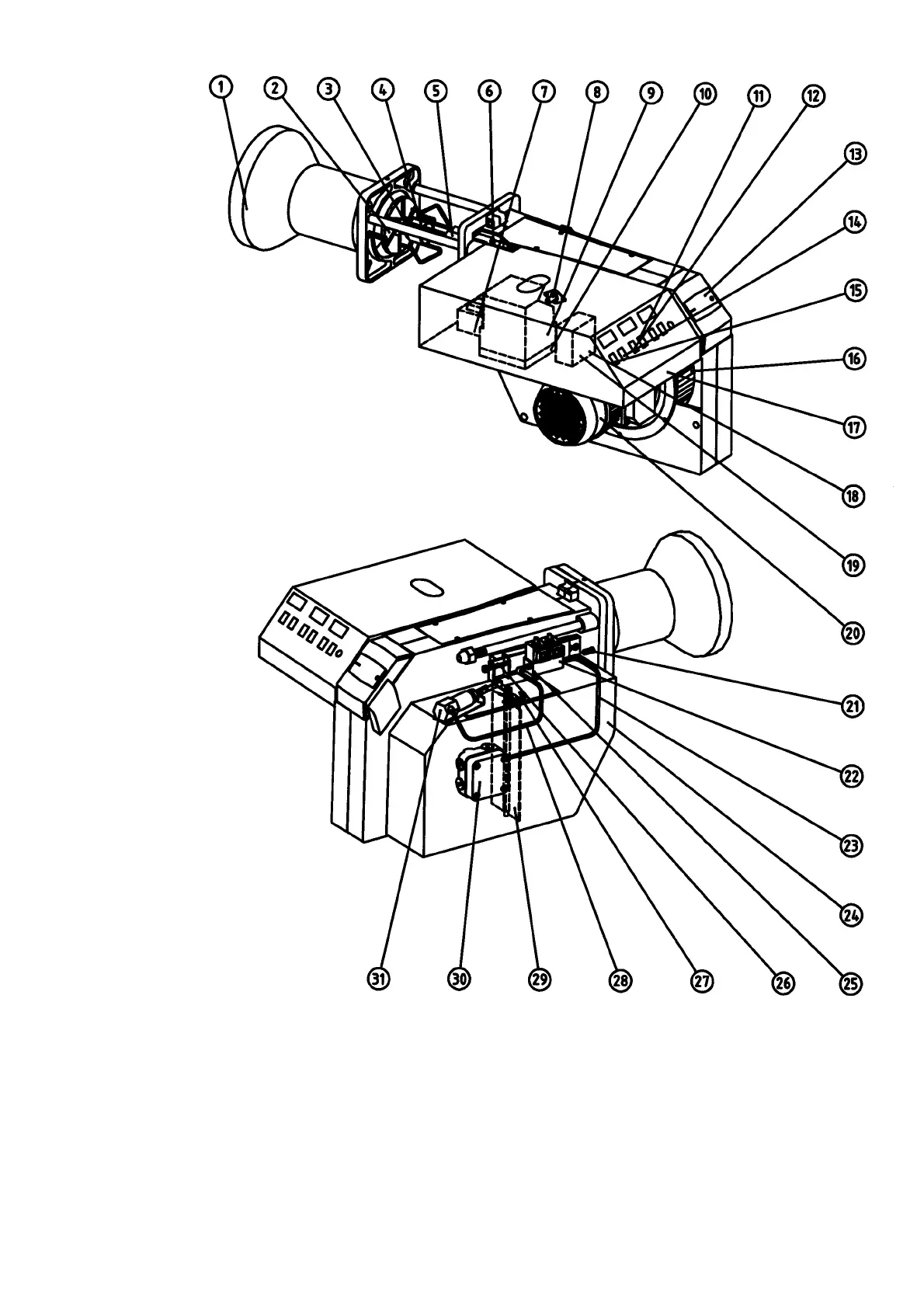
COMPONENTS
1. Flame cone
2. Shrouded disc
3. Nozzle
4. Nozzle assembly
5. Ignition electrodes
6. Ignition cable
7. Ignition transformer
8. Photocell
9. Control box
10. Front plate, relay base
11. Switch l-ll
12. Indicating lamp Stage 2
13. Cover, inspection glass
14. Indicating lamp Stage 1
15. Switch 0-l
16. Fan wheel
17. Electric panel
18. Contactor
19. Thermal overload protection
20. Motor
21. Locking device, flange
22. Solenoid valves
23. Connecting pipe
pump-solenoid valve bloc
24. Air intake
25. Solenoid valve bloc
26. Nozzle assembly adjustment
27. Scale, air regulation
28. Connecting pipe, solenoid valve
bloc-adjustment device
29. Air damper
30. Pump
31. Adjustment device