ENFORCER Two-Channel RF Receiver
SECO-LARM U.S.A., Inc. 3
SK-910RB2Q shown. SK-910RBQ is the
same, but only has one each: mode
switch; function switch; indicator LED;
channel relay.
Channel Mode Switch Operation (One per Channel):
LED Indication (One per Channel):
Extended Range Antenna (Optional):
The SECO-LARM SK-91ERSDQ extends RF receiver range up to
1,000ft (304m) (open air) with existing remotes. It comes with a 9ft
(2.7m) cable that easily plugs into the 3-pin antenna port located on the
RF receiver.
Note:
If an extended range antenna is used, the ―LP3‖ on the receiver PC
board must be cut.
Actual antenna range will vary greatly depending on the operating
environment.
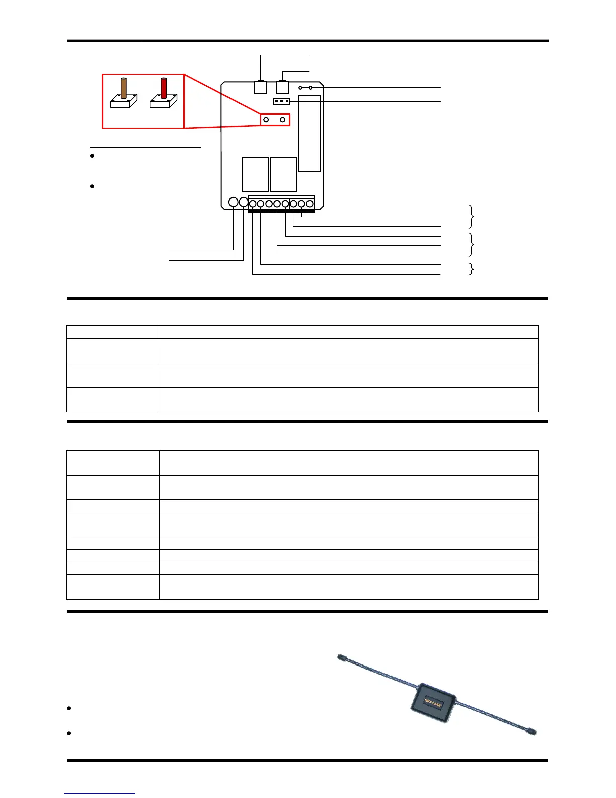
(PC board shown. Remove the front cover of the receiver to access the function switch(es) and terminal block.)
Press and hold the channel mode switch for three seconds or more.
Press and hold the channel mode switch for three seconds or more, then when the LED starts
flashing, press again for three seconds to delete all previously learned codes.
If the channel was programmed for latch output, once the relay is turned ON with a transmitter
button, press the channel mode switch of that channel once to turn the relay OFF.
Press and release the channel mode switch to show the number of codes stored. The LED will
flash a number of times corresponding to the number of codes stored.
Receiving signal from a transmitter button during normal operation, or indicates a transmitter
button’s code already exists in the receiver’s memory during code learning.
Receiver is in code-learning mode or channel memory display mode, or during the programming
channel output mode.
A transmitter button code was learned, or receiver channel is in 4-second timed output mode.
All previously learned transmitter buttons were deleted, or receiver channel is in toggle output
mode.
Receiver channel is in latched output mode.
Receiver channel is in validity output mode.
Receiver channel is in 1-second timed output mode.
During normal operation, pressing a channel mode switch will cause the channel indicator LED
to flash. Number of flashes indicates the number of transmitter buttons currently stored.
Brown function switch is
for channel 1 programming.
Red function switch is for
channel 2 programming.
Channel Function Switches
 Loading...