A HE, DE & RE MANUAL
IOM-26 17 of 33 Oct 12 R4
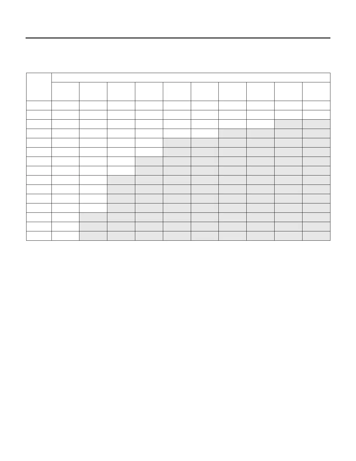
Recommended 24V Field Wiring Size:
Copper conductors only
Maximum Total Length of Run
Notes:
1) The field wiring load depends on the actual load on a particular control circuit the field wiring is
connected to. Refer to the internal wiring diagram of the unit.
2) The table above is based on a maximum 10% voltage drop on a 24V control circuit. Wire size was
calculated using the following formula:
CM = (25 x I x L ) / V
Where CM is circular mils of conductor for a constant load of I amps, wire length L in feet from the
unit to the field device and back, and voltage drop V.
When connecting to a three phase power supply, check for the correct rotation of all motors and fans. If the
rotation is incorrect, reverse the rotation at the incoming power only. All electrical conduit outlets in the
control panel must be sealed to prevent moist building air from migrating to the control panel.
All penetrations through the unit walls must be caulked and sealed to prevent air and/or water from
entering the unit.
 Loading...