Do you have a question about the Engel HBI3260 and is the answer not in the manual?
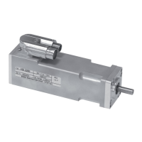
Provides detailed technical specifications for the integrated control electronics of the drives.
Provides crucial information for operation, including regenerative operation and service life.
Explains regenerative operation, its effects on voltage, and required measures for energy management.
Details the integrated sensor equipment for monitoring and safety shutdown of the drive.
Describes how to operate the drive in speed control mode using various setpoint sources.
Details positioning functionality using digital inputs and outputs in I/O mode, including target storage.
Procedure for detecting a defined machine position using various homing methods.
How limit switches function as movement range limitation and reference switches.
Details the functions of the 8 digital inputs and their assignment based on operating mode.
Describes the functions of the two digital outputs and their configuration options.
Details the pin assignment and functions for the X1 connector (supply and signals).
Details the pin assignments for the X2a connector used for CAN communication.
Details the pin assignments for the X2b connector for incremental encoder output signals.
An example diagram illustrating the connection of HBI drives, showing wiring and connectors.
Lists possible error codes displayed by the drive, their meaning, and measures for rectification.
Guides the user through the process of adjusting speed controller parameters for optimal performance.
| Brand | Engel |
|---|---|
| Model | HBI3260 |
| Category | Servo Drives |
| Language | English |