A DJ & DG MANUAL
14 of 34 May 12 R2
The unit must be electrically grounded and all wiring must be installed in accordance with the National
Electrical Code, ANSI/NFPA 70, and/or the Canadian Electric Code CSA 22-1 and to the approval of the
authorities having jurisdiction. THE FLOOR OF THE UNIT HAS BEEN MADE WATER-RESISTANT. DO
NOT CUT OR DRILL HOLES IN THE FLOOR OR USE PENETRATING FASTENERS. Field wiring
diagrams, internal wiring diagrams and operating functions are included in the control cabinet. The power
requirements are indicated on the rating plate. Where field wiring of control circuits is required, take care to
size the field wiring for a maximum 10% voltage drop. The control circuit ampacity is noted on the field
wiring diagram. See the field wiring diagram for requirements for shielded or twisted pair wire for solid state
devices.
Caution:
m
Temporary Power Generation
The warranty will be void if the voltage being fed from any temporary
generator is not within 10% of the nominal rated nameplate voltage and
voltage imbalance shall be limited to 2%. A power monitor shall be installed
by others to properly monitor power quality and conditions.
All generator sets shall be provided with overcurrent and earth-fault
protection. The protective apparatus should be capable of interrupting,
without damage, any short-circuit current that may occur.
Warning:
m
No unspecified external load shall be added to the control transformer
circuit(s) or to the main power circuit(s).
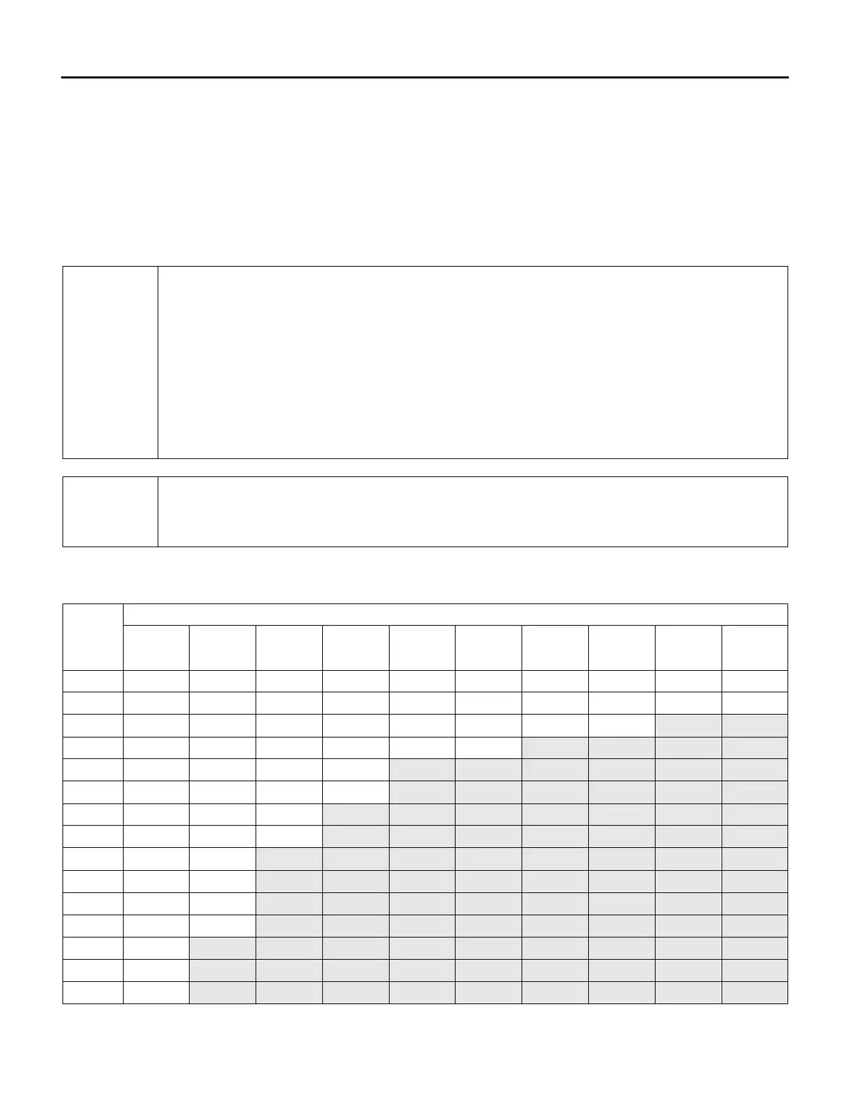
Recommended 24V Field Wiring Size:
Copper conductors only
Maximum Total Length of Run
< 50 Ft
< 100 Ft
< 150 Ft
< 200 Ft
< 250 Ft
< 300 Ft
< 350 Ft
< 400 Ft
< 450 Ft
< 500 Ft
Circuit
Load
(Amps)
(1)
(~ 15 m)
(~ 30 m)
(~ 45 m)
(~ 60 m)
(~ 75 m)
(~ 90 m)
(~ 105 m)
(~ 120 m)
(~ 135 m)
(~ 150 m)
1 16 AWG
16 AWG
16 AWG
16 AWG
16 AWG
16 AWG
14 AWG
14 AWG
14 AWG
12 AWG
2 16 AWG
16 AWG
16 AWG
14 AWG
12 AWG
12 AWG
12 AWG
10 AWG
10 AWG
10 AWG
3 16 AWG
16 AWG
14 AWG
12 AWG
12 AWG
10 AWG
10 AWG
10 AWG
4 16 AWG
14 AWG
12 AWG
10 AWG
10 AWG
10 AWG
5 16 AWG
12 AWG
12 AWG
10 AWG
6 16 AWG
12 AWG
10 AWG
10 AWG
7 14 AWG
12 AWG
10 AWG
8 14 AWG
10 AWG
10 AWG
9 14 AWG
10 AWG
10 12 AWG
10 AWG
11 12 AWG
10 AWG
12 12 AWG
10 AWG
13 12 AWG
14 12 AWG
15 12 AWG
Notes:
 Loading...