A CU MANUAL
IOM-14 25 of 46 Feb 06 R4
10. Pressurize the system to a slight positive pressure, (one or two psig). Replace all Schraeder valve
cores. Do not allow air into the system.
11. Reinstall gauges, proceed to the start-up section for charging instructions.
NEVER use system compressors to evacuate a system. Operating a compressor while the
system is under a high vacuum may cause internal arcing of the windings and
compressor failure. Compressor damage caused by high vacuum operation is not
covered by system warranty.
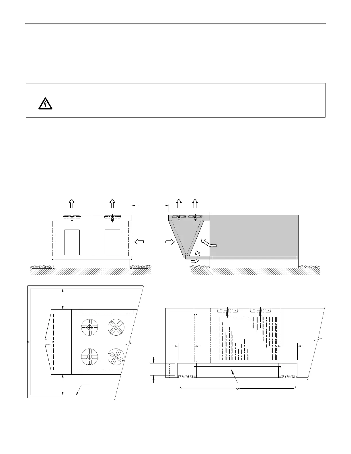
CLEARANCE FOR CONDENSER AIR FLOW
Proper air flow is essential for the operation of this equipment. Maintain at least 60” (1500 mm) clearance
between the condenser coil and any obstruction. Maintain at least 96” (2400mm) between adjacent
condensing sections. Do not place condenser sections in a well. Wells create a situation where air re-
circulates from the condenser fan back to the condenser coil. Enclosures must be designed for proper air
flow and to prevent blockage or re-circulated air.
CONDENSER COIL
CONDENSER SECTION
COMPRESSOR SECTION
2438mm
96" (MIN)
1524
60" (MIN)
1524
60" (MIN)
36" (MIN)
914
C
O
N
D
E
N
S
E
R
C
O
I
L
ENCLOSURE OR
OBSTRUCTION
CURB OR SUPPORTCURB OR SUPPORT
ELEVATION VIEW
ELEVATION VIEW
PLAN VIEW
CONDENSER COIL
CURB OR SUPPORT
610mm
24" (MIN)
12" (MIN)
305mm
DO NOT OBSTRUCT
CONDENSIGN UNIT
1219mm
48" (MIN)
CONDENSER COIL
CONDENSER COIL
C
O
N
D
E
N
S
E
R
C
O
I
L
 Loading...