Do you have a question about the Engineered air EngA W-TRAC and is the answer not in the manual?
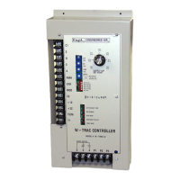
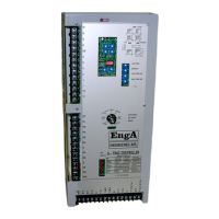
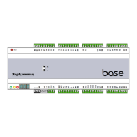
Overview of the W-TRAC supervisory controller for Engineered Air HRW heat wheels.
Details power requirements, contact rating, input impedance, and operating environment.
Covers property damage, injury, death risks from improper handling and electrical shock hazards.
Lists all controller terminals and their functions for proper connection.
Explains DIP switch settings for configuring W-TRAC operational options.
Describes the 5 red LED lights and their meanings for system status monitoring.
Details the setting and calibration potentiometers (POT's) on the controller face.
Explains the 4 operating modes (Heat, Defrost, Vent, Cool) for supply air control.
Describes setting the base discharge air temperature and using remote reset signals.
Explains preventing frost accumulation on the heat wheel by adjusting rotation speed.
Details using an exhaust RH% sensor for frost prevention with specific DIP settings.
Explains using a return air RH% sensor for frost prevention with specific DIP settings.
Describes using predicted RH% values and BDRH setting for frost control.
Provides requirements for power supply, wire gauge, and noise reduction for remote wiring.
Notes on checking heat wheel rotation direction for proper purge function.
Details 0-10Vdc motor speed control connection to controllers/inverters and DIP settings.
Explains W-TRAC output interaction with KBVF inverter via SIVF isolator.
Specifies factory set maximum and minimum heat wheel rotation speeds.
Steps to calibrate the discharge air temperature sensor using a POT and LED.
Steps to calibrate the exhaust air temperature sensor using a resistor and POT.
Describes measuring humidity sensor output against known RH values.
Provides a table of temperature vs. resistance values for the TE6000EA3 sensor.
| Brand | Engineered air |
|---|---|
| Model | EngA W-TRAC |
| Category | Controller |
| Language | English |