Page 2 Page 3 Page 4
Installation
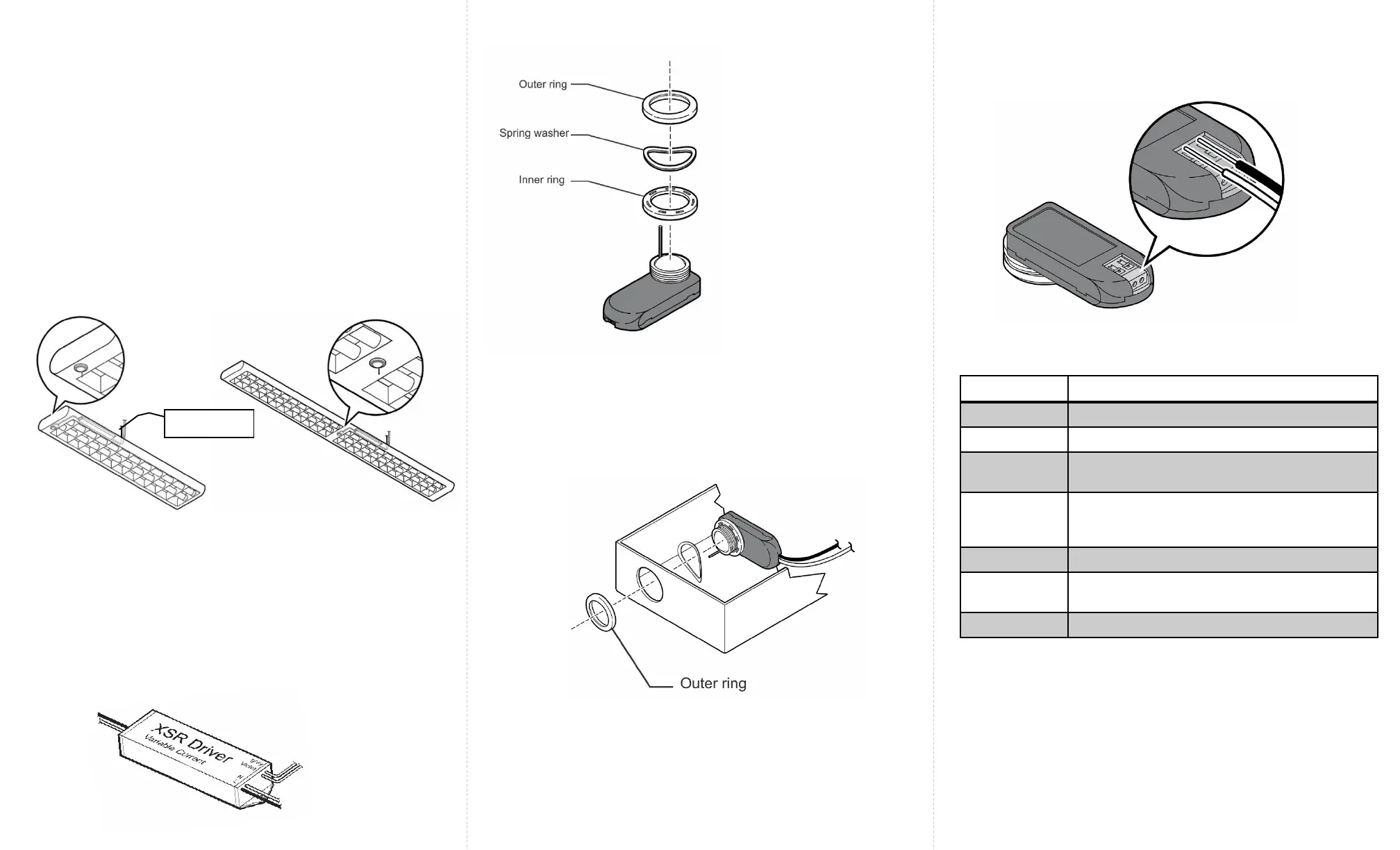
LED Description
Figure 4
Note: For any reason, if you need to remove the two wires,
push down on the tabs of the sensor with a pointed device,
and remove the wires while continuing to hold the tab down.
Sensor Antenna
To Enlighted
sensor
To
lamps
Figure 1
Figure 2
LED Status Description/Solution
LED not on Check power and wiring
Purple solid All LEDs are on during boot time for 5-6 seconds
Green
blinking
Sensor commissioned and working
Red blinking Incompatibility between LED driver and sensor –
Replace LED driver and if not resolved, replace
sensor.
Red solid Faulty sensor – replace sensor
Green solid Sensor installed, initialized, and
uncommissioned – waiting for discovery.
Blue solid Image being upgraded.
Figure 3
Figure 5
From Mains
The two-wire Fixture Mount sensor is designed to mount in a ½
inch trade size knockout. All parts of the sensor are inside the
lighting fixture except for the outer ring. (See Figure 4). This
sensor is for use with the Philips XSR driver.
Step 1: Switch off the circuit breaker supplying power to the
light fixture.
Step 2: Determine the location for the sensor in the fixture.
Step 3: Remove an existing ½ inch knockout or cut a hole in
the fixture.
Step 4: Measure the distance between the sensor’s installation
location and the LED XSR driver.
Caution
Installation and maintenance must be performed by a qualified
electrician in accordance with local, state, and national electrical
codes (NEC) and requirements.
Step 5: Cut two lengths of 18 AWG solid wire that are at least
this measured length plus one inch. Strip each end of the two
wires leaving 3/8 inch of exposed wire.
Step 6: Insert one end of the pair of wires into the LED XSR
driver’s connections wire holes. See Figure 2.
Step 7: Remove the outer ring
from the sensor by unthreading
it. Keep the spring washer and
inner ring on the sensor.
Step 9: Close the light fixture and restore power to the fixture.
Step 8: Insert the sensor assembly into the knockout that was
cut out of the light fixture. Thread the outer ring back on the
sensor. Tighten firmly, but do no over tighten. If you have a
thick fixture, do not use the inner ring.
Note: Make sure that the sensor antenna passes through the
knock out and does not get caught in the rings or assembly.
LED Driver
Sensor Antenna
 Loading...