Page 2
Page 3
Page 4
Tile Mount Sensor Installation
Figure 2
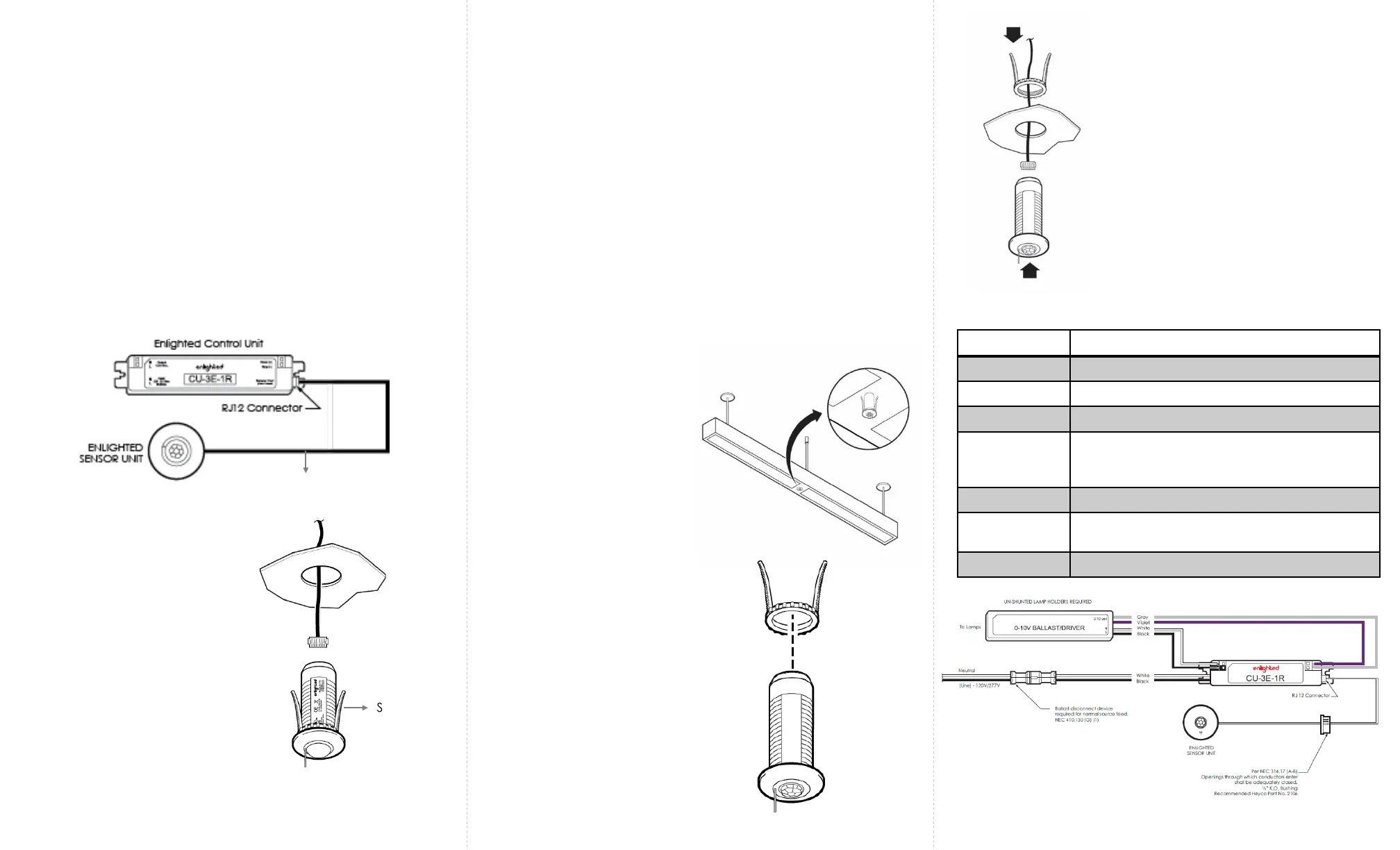
Fixture Mount Sensor Installation
Caution
Installation and maintenance must be performed by a qualified
electrician in accordance with local, state, and national electrical
codes (NEC) and requirements.
Spring Arms
Figure 4
Figure 3
LED Status Description/Solution
LED not on Check power and wiring
Purple solid All LEDs are on during boot time for 5-6 seconds
Green blinking Sensor commissioned and working
Red blinking Incompatibility between LED driver and sensor
– Replace LED driver and if not resolved,
replace sensor.
Red solid Faulty sensor – replace sensor
Green solid Sensor installed, initialized, and
uncommissioned – waiting for discovery.
Blue solid Image being upgraded.
LED Description
Step 1: Switch off the circuit breaker supplying power to the
light.
Step 2: Mount the Control Unit (CU) behind the ceiling tile or in
a UL approved enclosure. Refer to the Control Unit Installation
Guide.
Step 3: Connect the RJ-12 connector end of the Compact
Sensor cable to the Control Unit. See Figure 1. For a detailed
wiring diagram, see Figure 6.
Note: The sensor is designed to
mount in a 15/16
th
inch hole in
the ceiling tile.
Step 4: Make a small circular cut
in the ceiling tile.
Step 5: Pull the other 6-pin end of
the Compact Sensor cable
through the hole in the tile.
Figure 1
Step 6: Insert the end of the wire into the sensor’s 6-pin
connector. See Figure 2.
Step 7: Push the spring arms together and insert the sensor
through the hole in the tile. See Figure 2.
Step 8: Turn the power on by switching on the circuit
breaker.
Step 1: Switch off the circuit breaker supplying power to the
light.
Step 2: Mount the Control Unit (CU) in the ballast cavity of
the fixture or in a UL approved enclosure. Refer to the
Control Unit Installation Guide.
Step 3: Connect the RJ-12 connector end of the Compact
Sensor cable to the Control Unit. See Figure 1. For a detailed
wiring diagram, see Figure 6.
Step 5: Unthread the spring arms
from the Compact Sensor. See
Figure 4.
Step 8: Turn the power on by switching
on the circuit breaker.
Step 6: Insert the Compact Sensor
through the hole in the fixture. Use the
spring arms from behind the sensor to
fasten the Compact Sensor.
See Figure 5.
Step 7: Insert the 6-pin end of the
Compact Sensor cable to the 6-pin
connector on the sensor. See Figure 5.
Step 4: Determine the
location for the sensor in the
fixture and cut a ½ inch
knockout in the fixture. See
Figure 3.
Figure 5
Figure 6
Compact
Sensor Cable
Note: The sensor is
designed to mount in a ½
inch trade size knockout on
a fixture.
 Loading...