Page 2
Page 3
Page 4
Step 1: Switch off the circuit breaker supplying power to the
light.
Step 2: Make a small circular 15/16
th
inch cut in the ceiling tile.
Step 3: Measure the distance between the sensor’s installation
location and the LED XSR driver.
Tile Mount Sensor Installation
LED Status Description/Solution
LED not on Check power and wiring
Purple solid All LEDs are on during boot time for 5-6
seconds
Green blinking Sensor commissioned and working
Red blinking Incompatibility between LED driver and sensor
– Replace LED driver and if not resolved,
replace sensor.
Red solid Faulty sensor – replace sensor
Green solid Sensor installed, initialized, and
uncommissioned – waiting for discovery.
Blue solid Image being upgraded.
LED Description
Note: For any reason, if you need to
remove the two wires, push down on
the tabs located on the rear of the
sensor with a pointed device, and
remove the wires while continuing to
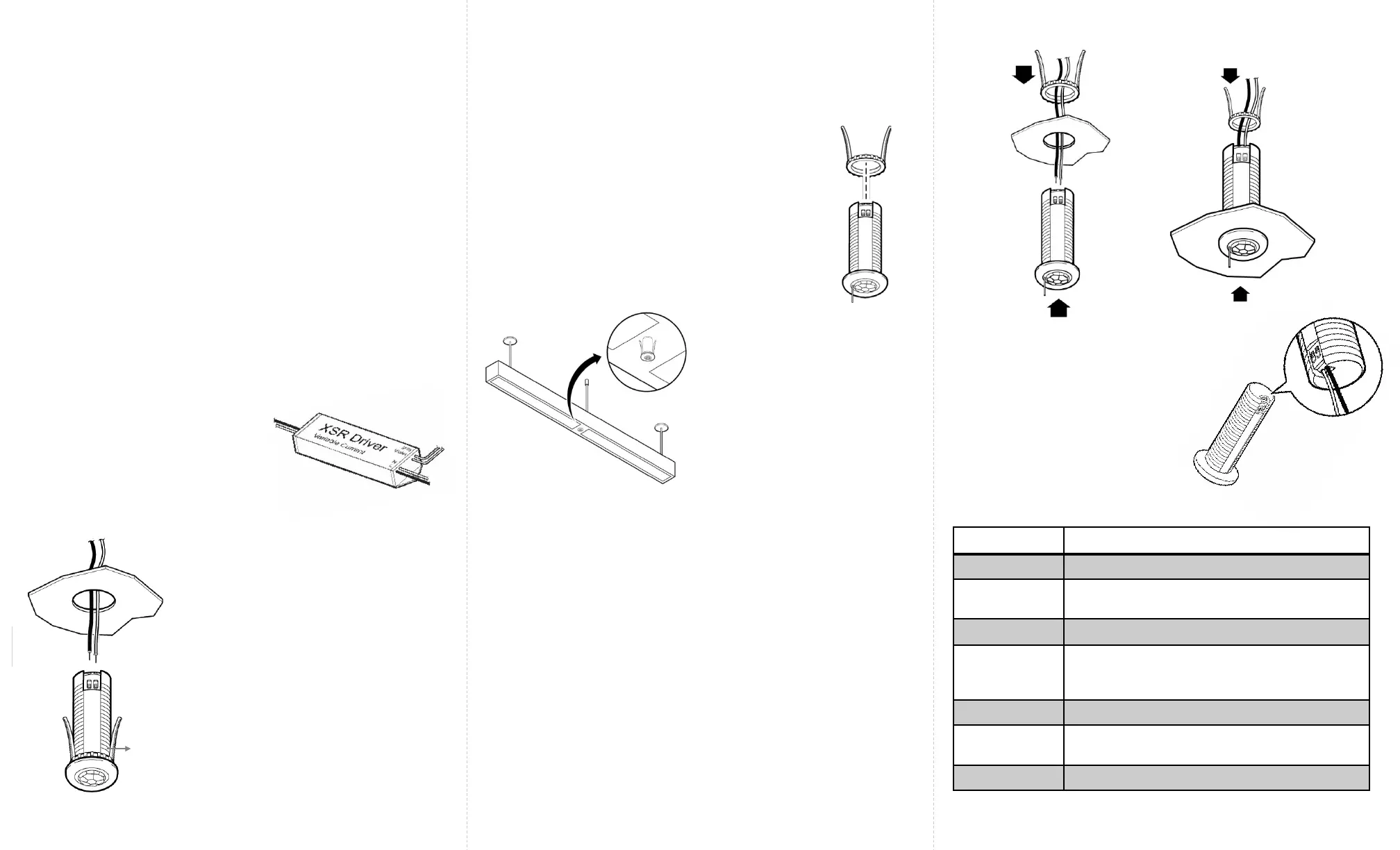
hold the tab down. Figure 7.
To Enlighted
sensor
Fixture Mount Sensor Installation
Caution
Installation and maintenance must be performed by a qualified
electrician in accordance with local, state, and national electrical
codes (NEC) and requirements.
To
lamps
Figure 7
Figure 5
From Mains
The CSD2 sensor is designed to mount in a 15/16
th
inch hole in
the ceiling tile. The sensor is for use with the Philips XSR driver.
This sensor is for use with the Philips XSR driver.
Step 6: Pull the other end of the
wires through the hole in the tile
and insert the wires into the sensor’s
holes. See Figure 2.
Figure 1
Figure 2
Step 7: Push the spring arms
together and insert the sensor
through the hole in the tile. See
Figure 2.
Step 8: Turn the power on by
switching on the circuit breaker
.
Spring
Arms
Step 1: Switch off the circuit breaker supplying power to the
light.
Figure 4
Note: The sensor is designed to mount in a
½ inch trade size knockout on a fixture.
Step 3: Determine the location
for the sensor in the fixture and
cut a ½ inch knockout in the
fixture. Figure 4.
Step 2: Unthread the spring arms from the
sensor. Figure 3.
Figure 3
Step 7: Pull the other end of the wires through the hole in the
fixture. Figure 5
Step 8: Insert the sensor through the hole in the fixture.
Step 9: Use the spring arms from behind the sensor to fasten
the sensor to the fixture. Figure 6.
Step 4: Measure the distance between the sensor’s
installation location and the LED XSR driver.
Step 5: Cut two lengths of 18 AWG solid wire that are at least
this measured length plus one inch. Strip each end of the
two wires leaving 3/8 inch of exposed wire.
Step 6: Insert one end of the pair of wires into the LED XSR
driver’s connections wire holes. See Figure 1.
Step 5: Insert one end of the pair
of wires into the LED XSR driver’s
connections wire holes. See
Figure 1.
Step 4: Cut two lengths of 18 AWG solid wire that are at least
this measured length plus one inch. Strip each end of the
two wires leaving 3/8 inch of exposed wire.
Figure 6
 Loading...