Page 2 Page 3 Page 4
Installation
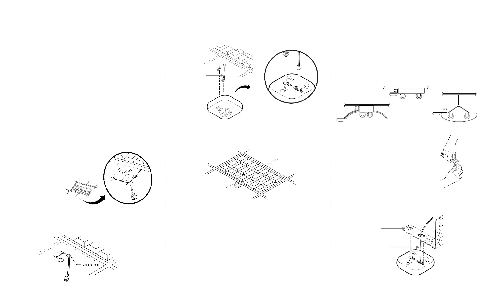
Figure 1
Caution
Installation and maintenance must be performed by a qualified
electrician in accordance with local, state, and national electrical
codes (NEC) and requirements.
Step 1: Turn off all power to the light fixture by switching off
the circuit breaker.
Step 2: Mount the Control Unit (CU) in a UL approved
enclosure. Refer to the Control Unit Installation Guide for
installation and wiring instructions. The sensor cable,
terminating in an RJ12 connector, from the CU will need to
connect to the Smart Sensor.
Step 1: Determine the location of
the sensor. Push and rotate the
anchor screw to the tile at that
location.
Step 3: Connect the sensor cable’s RJ12 connector to the
sensor bottom.
Step 4: Align the anchor screw with the slot provided on the
sensor bottom. Slide the Smart Sensor onto the screw head.
Step 5: Slip the excess sensor cable up into the plenum area
and adjust the ceiling tile to the original position.
Step 6: Switch on the circuit breaker to turn the power on.
Figure 4
Anchor Screw
Sensor Cable
The Smart Sensor (SU-4S) should be mounted to the ceiling
tile within a few inches (between 1
3/4
” to 3”) of the lighting
fixture.
The Smart Sensor can be mounted to ceiling tiles using an
anchor screw or to pendant and industrial fixtures using the
adjustable mounting bracket.
Mounting using an Anchor Screw
Mounting using the Adjustable Mounting Bracket
The Smart Sensor (SU-4S) can be mounted on pendant
and industrial fixtures using the mounting bracket.
Step 1: Determine the mounting location of the sensor on
the fixture. To ensure that the view of the sensor is not
obstructed by the fixture, level the sensor to the bottom of
the fixture and provide enough clearance from the fixture.
See examples below.
Step 2: Bend the adjustable
mounting bracket to the required
shape. Fasten the bracket to the
fixture using two 8” screws.
Figure 5
Figure 6
Figure 7
Step 3: Connect the sensor cable’s RJ12 connector from
the CU to the bottom of the Smart Sensor.
Sensor Cable
Mounting
Bracket Head
Step 2: Select a place near the anchor screw for the RJ12
connector of the sensor cable from the CU to exit. Make a
small cut in the ceiling tile for the cable to exit.
Figure 2
Figure 3
 Loading...