Do you have a question about the Enraf Tanksystem HERMetic UTImeter Rtex and is the answer not in the manual?
| Brand | Enraf Tanksystem |
|---|---|
| Model | HERMetic UTImeter Rtex |
| Category | Measuring Instruments |
| Language | English |
Details of items included in the product shipment.
Procedure for checking the instrument upon receipt for completeness and damage.
Terms and conditions of the product warranty, duration, and coverage.
Information regarding the instrument's certifications and approvals.
Guidelines for returning units or parts for service and repair.
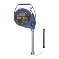
General overview of the HERMetic instrument, identification, and basic functions.
Detailed description of the ULTRA sensing probe, its components, and capabilities.
Information about the ETFE coated tape, its functions, and graduations.
Explanation of the mechanical safety device for protecting the tape and valve.
How the reading index indicates distance and potential corrections needed.
Description of the tape cleaner's function and operation for draining liquid.
Details on the optional additional load for specific gauging scenarios.
Miscellaneous components and features of the instrument like the reel and frame.
General overview of the gauging system, components, and installation considerations.
Specific installation example for a pipe connection using Q2 connector.
Specific installation example for a deck connection using Q2 connector.
Specific installation example for a pipe connection using Q1 connector.
Specific installation example for a deck connection using Q1 connector.
Explanation of the basic operation and functions of the 5-key control pad.
Guide on how to select the display language (English, German, French).
Instructions for changing the temperature display between Celsius and Fahrenheit.
Procedure for selecting the display resolution for temperature readings.
Details on how to activate the LED indicator in temporary or permanent modes.
Instructions on how to mute the instrument's buzzer and its automatic reactivation.
How to activate the display backlight and its automatic shut-off feature.
Pre-operation tests to ensure the instrument is ready and functioning correctly.
Steps for coupling the HERMetic instrument to a certified valve and initial checks.
Procedure for performing ullage and interface level measurements with the instrument.
Method for measuring reference height and innage using the additional load option.
Detailed procedure for taking accurate temperature measurements with the instrument.
Guidelines for cleaning and storing the instrument properly after use.
How to check the battery status and indicators for low power.
How to check battery power while the unit is operating.
Instructions for safely replacing the instrument's battery.
Step-by-step guide for replacing the instrument's tape assembly.
Procedure for disconnecting and connecting the sensing probe during replacement.
How to replace the tape wipers and remove the tape cover for maintenance.
Instructions for replacing the display unit of the instrument.
Guidelines for periodic inspection and verification of tape accuracy and integrity.
Process for verifying and adjusting the reading index for accurate measurements.
How to perform a temperature accuracy check using an ice point bath.
Method for verifying the instrument's ullage and interface detection capabilities.
Procedures for checking the tape assembly's grounding, short-circuit, and continuity.
Guide for performing a visual check of the instrument for damage or missing components.
Simple procedure to address stiff winding action of the tape.
Safety precautions to be observed when troubleshooting the instrument.
Troubleshooting common issues related to the instrument's power supply.
Solutions for issues related to data transmission between components.
Troubleshooting common problems encountered during ullage and interface measurements.
Solutions for issues related to temperature readings or sensor functionality.
Instructions on how to identify and order spare parts using TS numbers.
A table listing spare parts with their TS numbers and descriptions.
References to drawings illustrating the spare parts and their assemblies.
A list of available valve types with their corresponding ND and TS numbers.
Formal statement declaring the product's conformity with relevant EC Directives.
