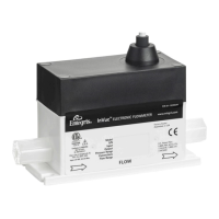
The InVue® Electronic Flowmeter, Model NT4400, is a high-purity flow measurement instrument designed for semiconductor industry applications and compatibility with highly corrosive processes. It measures fluid flow rate without moving parts or fill-fluids, minimizing the risk of process contamination. The flowmeter calculates fluid flow from the differential pressure measured by two sensors separated by a venturi-style integral orifice. It provides two optically isolated analog 4–20 mA electrical output signals: one for flow rate and another for pressure measurement, with the pressure measurement taken from the outlet of the flowmeter.
Function Description:
The NT4400 operates by measuring the differential pressure across an integral venturi-style orifice. This differential pressure is then used to calculate the fluid flow rate. The device also measures the static line pressure at the outlet. The output signals are standard two-wire 4–20 mA, requiring a 24 VDC (12–28 VDC) power supply with less than 2% ripple at 100 or 120 Hz. The flowmeter is designed to be mounted in an indoor, climate-controlled environment.
Important Technical Specifications:
Physical Specifications:
- Wetted parts: Body made of PTFE; Sensor interface made of CTFE or PFA (consult factory for specific material); O-rings made of Kalrez® 6375 UP.
- Nonwetted parts: Polypropylene, Polyethylene, Viton®, and PVDF.
- Connection type: Flaretek® tube fitting (standard); PrimeLock® and Super 300 Type Pillar® connections available upon request.
- Electrical connection: 12', 8-wire FEP-jacketed pigtail or polypropylene removable connector with 6' or 12' PVC-jacketed cable.
- Electrical enclosure: IP54.
- Certifications: ETL listed for conformance to UL 61010-1 and ANSI®/ISA® 12.12.01 standards for use in Class I, Division 2 Group A-D, T6 10°C ≤Ta ≤65°C, hazardous environments.
- Dimensions: Vary by connection size (e.g., for 1/4" Flaretek: A=151.9 mm (5.98"), B=86.4 mm (3.40"), C=19.6 mm (0.77")).
Electrical Specifications:
- Nominal input voltage: 24 VDC.
- Input voltage range: 12–28 VDC.
- Input current: 50 mA (max.) (+20 mA +20 mA for each output signal).
- Signal output range for flow and pressure: 4–20 mA (externally powered with 24 VDC. Output varies proportionately with flow or pressure measured).
- Maximum load resistance: 0 Ω at 12 VDC, 800 Ω at 28 VDC.
- Maximum output current: 22 mA for flow signal, 22 mA for pressure signal.
- Process temperature: 10° to 65°C (50° to 149°F).
- Ambient temperature: 10° to 65°C (50° to 149°F).
- Storage temperature: -15° to 40°C (20° to 149°F).
- Minimum operating pressure (at the outlet): 7 kPa (1.0 psig).
- Maximum operating pressure: 414 kPa (60 psig).
- Pressure drop: 21 kPa (3 psid) at 80% flow (10:1 turndown); 21 kPa (3 psid) at 40% flow (20:1 turndown).
- Response time: 50 msec update rate.
- Flow accuracy (10:1 turndown, T flow ranges): 20–100% of range ±1.0% of full scale; 10–20% of range ±2.5% of full scale*.
- Flow accuracy (20:1 turndown, E flow ranges, legacy): 10–100% of range ±1.0% of full scale; 5–10% of range ±2.5% of full scale.
- Accuracy stated as full scale using deionized water at 23°C (73°F) and includes combined effects of linearity, hysteresis, and repeatability.
- Flow repeatability (10:1 turndown, T flow ranges): 20–100% of range ±0.5% of full scale; 10–20% of range ±1.0% of full scale.
- Flow repeatability (20:1 turndown, E flow ranges, legacy): 10–100% of range ±0.5% of full scale; 5–10% of range ±1.0% of full scale.
- Pressure measurement range: 0–414 kPa (0–60 psig).
- Over-pressure limit: 690 kPa (100 psig).
- Pressure accuracy: ±1.0% of full scale, includes combined effects of linearity, hysteresis, and repeatability.
- Pressure repeatability: ±1.0% of full scale.
- Note: A performance loss up to 10% FS accuracy error may occur when the unit is exposed to radiated radio frequency fields of 10 V/m in the frequency range of 730–970 MHz range or conducted radio frequency of 3V in the 10–15 MHz range.
Usage Features:
- Installation: The flowmeter is factory sealed, and any attempt to remove the cover will void the warranty. Proper tubing size and fittings (Flaretek® standard, PrimeLock® and Super 300 type Pillar® available) must be used. Care should be taken to avoid excessive torque or high heat during installation. The flowmeter and base bracket assembly must be mounted to a solid surface to ensure stability and freedom from mechanical stress.
- Flow Direction: It is crucial to connect the flowmeter correctly, ensuring process fluid enters at the inlet and exits at the outlet. Incorrect installation will result in erroneous flow and pressure signals.
- Downstream Valve: A two-way valve must be installed downstream from the flowmeter to perform the re-zero function.
- Mounting Orientation: The NT4400 can be mounted in any orientation and does not require straight lengths of tubing at the inlet or outlet. For best performance, it should be mounted at a relative elevation lower than the point-of-dispense to maintain positive pressure.
- Operating Pressure: A minimum of 7 kPa (1.0 psig) of pressure must be present on the outlet side for the flowmeter to perform within specification. Maximum pressure is 414 kPa (60 psig).
- Electrical Connections: Input and output signals are supplied via an 8-wire FEP-jacketed pigtail or an optional 8-wire removable PVC-jacketed electrical connector (D-Series connector). Power supply must be clean and dedicated to measurement-type devices, avoiding inductive loads to prevent transients. Return lines should not be run within the same conduit or cable as signal lines.
- Hazardous Locations: Conforms to UL 61010-1 and ANSI®/ISA® 12.12.01 standards for use in Class I, Division 2 Group A-D, T6 10°C ≤Ta ≤65°C environments.
Maintenance Features:
- Normal Operation: Requires no maintenance other than a periodic re-zero of the flowmeter.
- Flowmeter Re-zero Function: This function allows resetting the analog output corresponding to zero flow.
- Procedure:
- The re-zero function requires the same 24 VDC (12–28 VDC) power supply used to power the unit.
- Stop the process fluid flow completely (typically by closing a process valve on the outlet side).
- Verify a minimum of 7 kPa (1.0 psig) [414 kPa (60 psig) maximum] of stable static line pressure using the pressure output signal. Best results are achieved when re-zero is performed at the operating pressure.
- Apply 24 VDC (12–28 VDC) to the violet wire for a minimum of three seconds, using the same ground as the flowmeter's power supply.
- Automation: The re-zero procedure can be automated using switches, a PLC, or other logic controller devices.
- Frequency: For best performance, the re-zero function should be performed daily when operating at ambient temperatures, more often at higher temperatures, after start-up, and after fluid temperature changes greater than 5°C (9°F). Re-zeroing between each dispense cycle is recommended for optimal performance.
- Troubleshooting: Diagnostics are performed by measuring the 4–20 mA output signal with a battery-powered current/voltage meter. A diagnostics guide is provided to address common issues such as incorrect installation, insufficient line pressure, noisy output, or wiring problems.