NETWORK ANALYSER
MPR-53/53S
6
NETWORK ANALYSER
MPR-53/53S
3
Press ESC button one by one until (SAU E SEt yES) is displayed.
Press SET button. When SAU E SEt yES is displayed, if you
press ESC button or choose no option instead of yES option
by using UP-DOWN buttons, new data will be cancelled and
previous value will be activated.
Press SET button for 3 seconds (trA Fo menu is displayed)
By using UP-DOWN buttons, find Pýn menu.
Press SET button (Pýn ACt IUA tE
menu is displayed.)
Press SET button (First digit blinks)
Enter the values for blinking digits by using UP-DOWN buttons,
switch to other digits by using SET button use BACK button
to switch to previous digit Pýn ACt oF is displayed. on can
be selected by using UP / DOWN buttons. (Data is entered
but is not activated yet. For activating the new data please follow
below steps)
Activating the user password:
This menu is used for activating the user password.
After the user password is activated, while the instant values
are observed,user password is required in order to enter to
the menu. If the wrong user password is entered, user can
not enter to the menu.
Note: Factory default value of user password is 0000
Press SET button.
(Data is entered but is not activated yet.
For activating the new data please follow the below steps)
Press ESC button one by one until SAU E SEt yES is
displayed.
Press SET button. When SAU E SEt yES is displayed, if you
press ESC button or choose no option instead of yES option
by using UP-DOWN buttons, new data will be cancelled and
previous value will be activated.
Press SET button for 3 seconds (trA Fo menu is displayed)
By using UP-DOWN buttons, select
Eng Cnt E-1 / Eng Cnt E-2.
Press SET button. (on blinks)
By using UP-DOWN buttons, select required parameter.
By using UP-DOWN buttons, find Eng Cnt menu.
Press SET button (Eng Cnt E-1 menu is displayed)
For activating the user password, In the monitoring mode :
Energy Counter (Eng Cnt) Menu
MPR-53/53S has 2 energy counters :
Energy counter 1 (E-1), Energy counter 2 (E-2).
E-1 / E-2 have 4 parameters :
on : Activate E-1 / E-2 counters for energy counting without depending
on any parameter.
ý-1 : Activate E-1 / E-2 counters, when digital input 1 is on (=1).
ý-2 : Activate E-1 / E-2 counters, when digital input 2 is on (=1).
E-2: E-1 does not count when E-2 is activated. (Only for E-1)
E-1: E-2 does not count when E-1 is activated. (Only for E-2)
Note: Counting status is undefned if E-2 is selected on E-1 and if E-1 is selected on
E-2. When the status is defined as above, both energy counters count while digital
input is not on (=1), but if either one or both digital inputs are on (=1) then counters
will not count.
By using UP-DOWN-SET buttons, enter the new password
By using UP-DOWN-SET buttons, re-enter the new password.
By using UP-DOWN-SET buttons, enter the old password
In this menu user password is defined and activated.
You must define and activate a 4 digit user password for
preventing device settings from the illegal usage.
There are 2 sub menus under the Pýn menu.
This menu is used to change the user password .
Note: Factory default value for user password is
0000
To change the user password,
In the monitoring mode :
Press SET button for 3 seconds (trA Fo menu is displayed)
Bu using UP-DOWN buttons, find Pýn menu.
Press SET button (Pýn ACt IUA tE menu is displayed)
By using the UP-DOWN buttons,
find Pýn CHA ngE menu.
User password Setup:
Changing of User Password:
Press SET button, Pýn CHA ngE is displayed. (Data is entered
but is not activated yet. For activating the new data please
follow the below steps).
Press ESC button one by one until (SAU E SEt yES) is
displayed.
Press SET button. When SAU E SEt yES is displayed, if you
press ESC button or choose no option instead of yES option
by using UP-DOWN buttons, new data will be cancelled and
previous value will be activated.
Pulse Menu
Press SET button for 3 seconds (trA Fo menu is displayed)
By using UP-DOWN buttons, select PUL SE rAt ýo,
PUL SE o-1 or PUL SE o-2.
By using UP-DOWN buttons, select required parameter.
By using UP-DOWN buttons, find PULSE menu.
Press SET button (PUL SE rAt ýo menu is displayed)
Press SET button.
(Data is entered but is not activated yet.
For activating the new data please follow the below steps)
Press ESC button one by one until SAU E SEt yES is
displayed.
Press SET button. When SAU E SEt yES is displayed, if you
press ESC button or choose no option instead of yES option
by using UP-DOWN buttons, new data will be cancelled and
previous value will be activated.
In this menu, three parameters can be selected :
PUL SE rAt ýo, PUL SE o-1, PUL SE o-2
PUL SE rAt : Pulse menu which is defined for how many pulses
deticated for energy consumption. PUL SE rAt value can be
assigned as below:
Press SET button (1k / A-I / r-L blink)
1, 10, 100 (wh/VArh/VA); 1, 10, 100 (kwh/kVArh/kVA); 1 Mwh/MVArh/MVA.
PUL SE o-1 / PUL SE o-2: 1 Pulse is taken for respected energy
consumption which assigned in PUL SE rAt. o-1 / o-2 can be assigned
as below :
ACt (Export/Import), A-I (Active Import), A-E (Active Export), rEA (Inductive
/ Capacitive), r-L (Reactive Inductive), r-C (Reactive Capacitive).
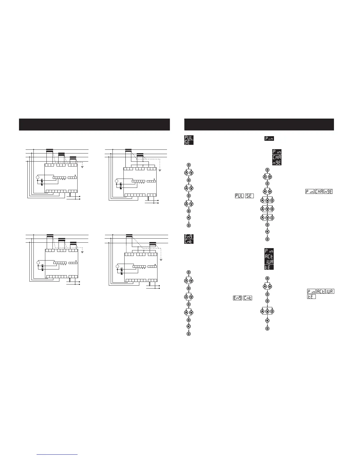
+
_
N
L1
L2
L3
1 A
L1
N
Current Measuring Input
Auxiliary
Supply
L1
L2
L3
N
12345
6
Voltage Measuring Input
k
l
KL
k
l
KL
k
l
KL
IL1
IL2
IL3
RS485
GND A T R
Max: 30 VDC
Pul 1 Pul 2
Pul C InC In1 In2
B
( 12-48V DC )
13 14 15 16 17 18 19 20 21 22
78910
11 12
3 Phase neutral
+
_
+
_
L1
L2
L3
1 A
L1
N
Current Measuring Input
Auxiliary
Supply
L1
L2
L3
N
12345
6
Voltage Measuring Input
k
l
KL
k
l
KL
IL1
IL2
IL3
RS485
GND A T R
Max: 30 VDC
Pul 1 Pul 2
Pul C InC In1 In2
B
( 12-48V DC )
13 14 15 16 17 18 19 20 21 22
78910
11 12
3 Phase without neutral current input with
Aron wiring configuration
+
_
L1
L2
L3
k
l
KL
k
l
KL
1 A
L1
N
Current Measuring Input
Auxiliary
Supply
L1
L2
L3
N
12345
6
Voltage Measuring Input
IL1
IL2
IL3
RS485
GND A T R
Max: 30 VDC
Pul 1 Pul 2
Pul C InC In1 In2
B
( 12-48V DC )
13 14 15 16 17 18 19 20 21 22
78910
11 12
3 Phase without neutral current input with
Aron wiring configuration
*Available only for MPR-53S
Note: For CT-25 models:
PR 19 Box Connection Diagram
3 Phase without neutral
L1
L2
L3
1 A
L1
N
k
l
KL
k
l
KL
k
l
KL
Current Measuring Input
Auxiliary
Supply
L1
L2
L3
N
12345
6
Voltage Measuring Input
IL1
IL2
IL3
RS485
GND A T R
Max: 30 VDC
Pul 1 Pul 2
Pul C InC In1 In2
B
( 12-48V DC )
13 14 15 16 17 18 19 20 21 22
78910
11 12
k: When CT-25 is used, Red cable is connected to k terminal.
l: When CT-25 is used, Black cable is connected to l terminal.
 Loading...