BEFORE STARTING
• Review all local building codes.
• Wear proper safety equipment.
STEP 1 GETTING STARTED
• Plumb all posts or mounting surfaces. Do not install post trim at this time.
Post trim should be installed at completion of railing installation.
• Determine required bottom rail height from deck surface to bottom of rail
based on local building codes.
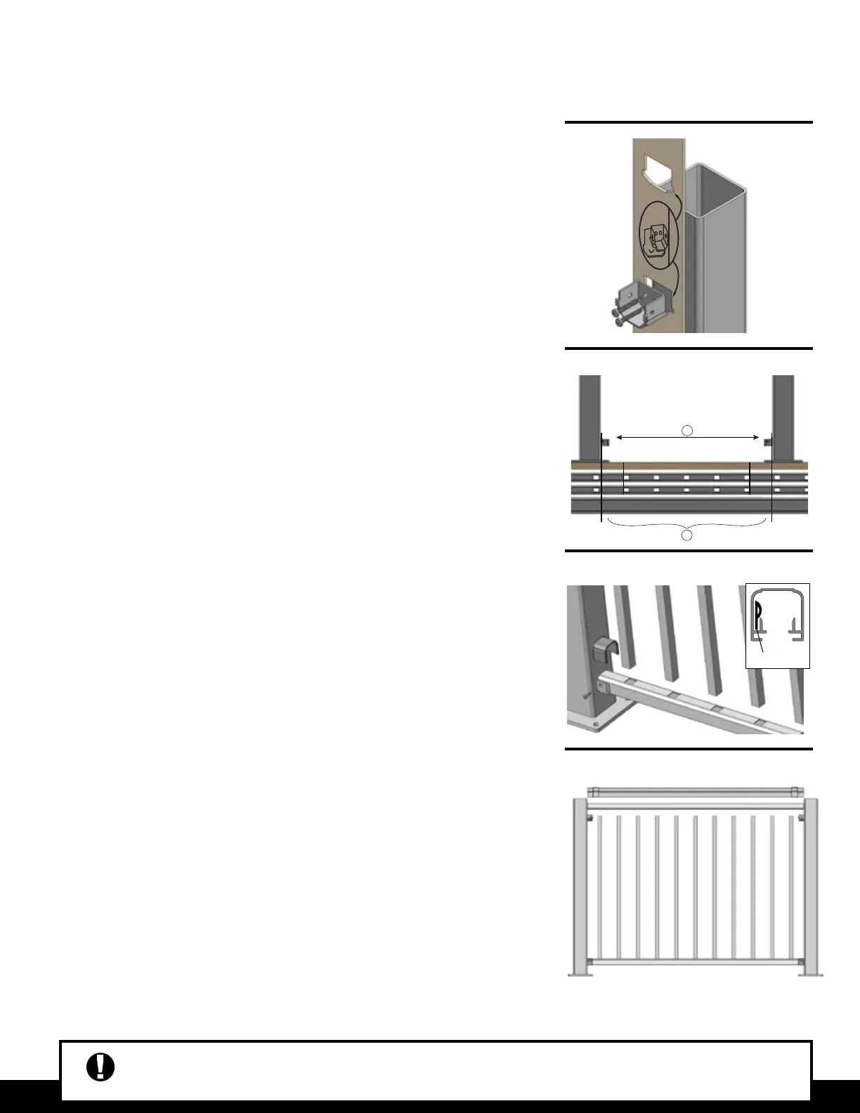
STEP 2 INSTALL MOUNTING BRACKETS
• Insert brackets into template per desired rail height – middle bracket hole location for
36” high railing, top bracket hole location for 42˝ high railing.
STEP 3 CUT RAILS & INSTALL BOTTOM RAIL
• Measure distance between inside mounting brackets.
• Mark bottom rail to correct length.
• Ensure there is equal & maximum distance from baluster holes on both
ends of top and bottom rails.
• Add 3/4" to bracket mark. Repeat for all top and bottom rail bracket marks.
• Cut bottom rail, top sub rail, and top cap rail the same length, ensuring baluster
holes line up.
• Slide bottom bracket cover onto both sides of the rail and set rail into place. Secure
rail by installing two #8 x 3/4" self-drilling screws through holes in both sides of
each bracket. Snap bracket cover over the bracket.
STEP 4 INSERT BALUSTERS
• Insert balusters into bottom rail making sure they are fully seated into rail.
• Make sure that the “P” insert remains within the bottom rail channel.
STEP 5 INSTALL TOP RAIL & PANELS
• Holding the sub rail at an angle above the baluster, start at one end to insert rst
baluster and tap lightly.
• Insert remaining balusters making sure they are seated completely in both
bottom and sub rails.
• Slide top bracket cover onto both sides of top rail. Place top cap rail over sub-rail.
• Secure rail by installing two #8 x 3/4” self drilling screws through holes in both
sides of each bracket. Snap bracket cover over the bracket.
STEP 6 FINISHING STEPS
• Tap post caps in place.
• Install two-piece, snap together trim.
• Measure to the underside of the bottom rail and cut rail support to measured length.
• Measure to the center of the bottom rail and secure rail support with 3/4” stainless
steel screw.
?"
=
A210
LEVEL INSTALLATION
STEP 2
STEP 3
STEP 4
STEP 5
Fairway Architectural Railing Solutions will not be held liable for incorrect or unsafe installations by the installer. It is the installer’s responsibility to secure
proper building permits, review local codes and safety needs and meet or exceed them. The instructions provided by Fairway are a guide and may not
account for every special circumstance. The installer must indentify and execute the installation approach that is appropriate for every application.
“P” Insert

 Loading...