© EnvisionTEC Page 2 of 4
TS-OPI-PCA-4000-V20210311-FN-EN.pdf
10 Once all four tray supports are in place, the post curing tray
can be lowered into the curing chamber, Fig. 5. Close the curing
compartment lid
11 Connect the power cable to the PCA 4000 and into a power
socket US - 110V / EU - 220V with a grounding socket. A controlled
switch socket is prefered as this would allow the operator to easily
disconnect the power to the apparatus when not in use - see Safety
Instructions
Powering on the PCA 4000
12 Once power cable is connected, the PCA 4000 can be powered
on via the power switch at the back of the unit.
The PCA 4000 will display a brief start-up screen and will then go
to stand-by mode. In this mode the PCA 4000 is ready to start the
required program. It is connected to power, but does not emit UV
rays while in stand-by mode - see Safety Instructions p. 4
Programs and Features
Main menu
Once the PCA 4000 is powered on, it automatically switches to the
Main menu. While in the Main menu, the curing oven is powered on
and ready to start the program selected by the user, but the LED lights
are not ignited.
Product Assembly
Unpacking the PCA 4000
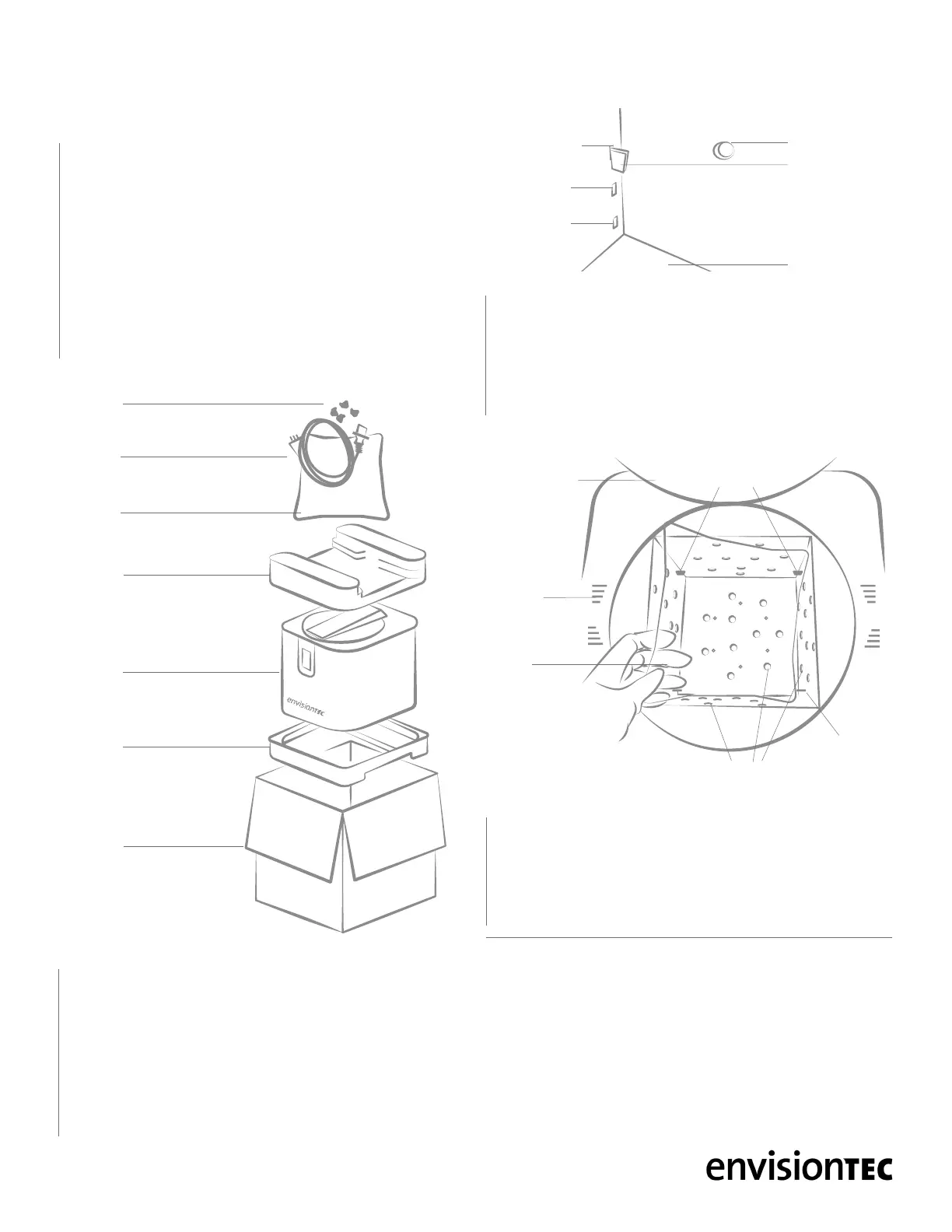
1 Carefully open the packaging: Do not use blades that could
damage the contents
2 Accessories for the PCA 4000 are packed on the top foam panel
- power cable, post curing tray, and tray supports to hold the post
curing tray in place, Fig. 3. Remove these from the box and set
aside
3 Extract the PCA 4000 from the box by lifting upwards
4 Remove the foam panels from the top and bottom
5 Do not throw away the box and foam panels. Keep the packaging
6 Situate the PCA 4000 on a secure surface. Place the PCA
4000 at a distance of at least 8 inches (20 cm) from any other
object, including the back wall. This is essential in order to avoid
obstructing the ducts of the PCA 4000’s cooling system - see
Safety Instructions p. 4
Installing the accessories
7 The post curing tray, Fig. 3, has a protective lm that will need to
be removed from both sides before installation. Always handle the
tray with gloved hands to avoid leaving nger prints
8 Locate the bag with the four small plastic tray supports, Fig. 3.
Remove these from their bag
9 In each corner inside the curing chamber there is a top hole,
middle hole, and bottom hole, Fig. 4. It is recommended to place
the tray supports in the top holes to ensure the models are an even
distance from all lights during the curing process. Open the curing
compartment lid, Fig. 1, and install the four tray supports in the four
top holes
00:00
Connected
Set
Program
CLEAR
BASIC
CUSTOM
CUSTOM
BASIC
CLEAR
START
Set Timer
00:02:00
START
Set Temp
20
°C
START
Set Power
100%
Program 0
Power
Temp
Time
START
100%
20
°
C
00:02:00
Set PRG
Prog: 0
Prog: 0
Prog: 1
Prog: 2
Prog: 3
Prog: 4
Prog: 5
Prog: 5
100%
100%
100%
100%
100%
100%
100%
30°C
30°C
30°C
30°C
30°C
30°C
30°C
00:10:00
00:10:00
00:10:00
00:10:00
00:10:00
00:10:00
00:10:00
Set PRG
PCA
4000
Foam
panel
Foam
panel
Box
Post
curing
tray
Power
cable
Tray
supports
PCA 4000 UNPACKINGFig. 3
PCA 4000 TRAY SUPPORTS POSITIONFig. 4
00:00
Connected
Set
Program
CLEAR
BASIC
CUSTOM
CUSTOM
BASIC
CLEAR
START
Set Timer
00:02:00
START
Set Temp
20
°C
START
Set Power
100%
Program 0
Power
Temp
Time
START
100%
20
°
C
00:02:00
Set PRG
Prog: 0
Prog: 0
Prog: 1
Prog: 2
Prog: 3
Prog: 4
Prog: 5
Prog: 5
100%
100%
100%
100%
100%
100%
100%
30°C
30°C
30°C
30°C
30°C
30°C
30°C
00:10:00
00:10:00
00:10:00
00:10:00
00:10:00
00:10:00
00:10:00
Set PRG
LED bulb
Tray
support
Base of curing
chamber
Top hole
Middle hole
Bottom hole
PCA 4000 INSTALLING POST CURING TRAYFig. 5
Time
00:01:00
Temp
20
°C
Time
START
00:01:00
Program
1
Temp
Power
60%
20
°
C
Power
35%
Time
START
00:01:00
E-Orthoshape
Main menu
Program
1
Program
2
Program
3
Program
4
Program
5
Program
6
Program
7
Program
8
Main menu
E-Orthoshape
E-Model HS E-SepFree
E-Tray Easy Cast
E-Shell
200 Series
PCA4000
30
°
C 35
°
C 40
°
C 45
°
C
STANDARDCUSTOM
Post
curing
tray
Cooling
ducts
Tray
supports
Curing
chamber lid
LED bulbs
Curing
chamber
 Loading...