EasyManua.ls Logo

EP Solar EPHC Series - User Manual

EP Solar EPHC Series
3 pages
Print Icon
To Next Page IconTo Next Page
Loading...
INSTRUCTION MANUAL
----------For solar charge controller,
----------EPHC series
INSTALLATION
Connect wires in order indicated 1— 6
Use with 12V batteries only
Use with 12V systems only
Do not exceed Solar and Load ratings (5A or 10A), depending on version
LED indicator
..
Green ON when solar is charging battery
Green blink when the system over voltage
...
Green ON when battery level in the right range
Green slowly flashing when battery level full
Yellow ON when battery level low
Red ON when loads cut off
...
Red ON when the output is on.
Red slowly flashing when its over load
(the load amps is 1.25 times of rated current for 60 seconds, or the load
amps is 1.5 times of rated current for 5 seconds)
Red fast flashing when the load is short-circuit.
...
Red ON when the switch is ON.
Red OFF when the switch is OFF.
Question and Answer IconNeed help?

Do you have a question about the EP Solar EPHC Series and is the answer not in the manual?

Overview

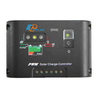
This document describes the EPHC series of PWM Solar Charge Controllers, designed for solar power systems.

Function Description

The EPHC series controller manages the charging of a battery from a solar array and controls the power supply to connected loads. It uses Pulse Width Modulation (PWM) for efficient charging and incorporates various protection mechanisms to ensure the longevity and safe operation of the system. The controller is designed to work with 12V battery and system configurations, with specific instructions for 24V systems (using 2x values).

Important Technical Specifications

Ratings (12V System)

  • EPHC-5: 80 Watts or 5 Amps for Solar and Load
  • EPHC-10: 170 Watts or 10 Amps for Solar and Load
  • Note: These ratings are for use with solar panels only.

Electrical Specifications (12V System)

  • Regulations Point: 14.4 Volts
  • Low Voltage Disconnect: 11.1V Volts
  • Low Voltage Reconnect: 13.1 Volts
  • Note: For 24V systems, all voltage values should be doubled (2x).

Charging Type

  • Method: Series PWM & State of Charge (SOC)
  • Stages: 4 stages: equalization, PWM, Boost, and Float.
  • Compensation: Temperature compensated charging.

Accuracy

  • Microcontroller digital accuracy.

Environmental & Mechanical

  • Tropicalization: Conformal coated printed circuit board.
  • Terminals: For wire sizes up to 4mm².
  • Weight: 250g
  • Dimensions: 140 x 90.5 mm (main body), 27.2 mm (depth).
  • Self-consumption: 6mA maximum.
  • Operating Temperature: -35 °C to 55 °C
  • Enclosure: IP22
  • Warranty: 3 years
  • Compliance: CE

Usage Features

Installation

  1. Connect wires in the specified order (1-6).
  2. Designed for 12V batteries and systems.
  3. Do not exceed the specified Solar and Load ratings (5A or 10A, depending on the version).

LED Indicator Meanings

  • Solar Charging Indicator:
    • Green ON: Solar is charging the battery.
    • Green blink: System over voltage.
  • Battery Level Indicator:
    • Green ON: Battery level is in the right range.
    • Green slowly flashing: Battery level is full.
    • Yellow ON: Battery level is low.
    • Red ON: Loads are cut off.
  • Load Output Indicator:
    • Red ON: Output is on.
    • Red slowly flashing: Overload condition (load amps are 1.25 times rated current for 60 seconds, or 1.5 times rated current for 5 seconds).
    • Red fast flashing: Load is short-circuit.
  • Switch Indicator:
    • Red ON: Switch is ON.
    • Red OFF: Switch is OFF.

Automatic Recovery from Over-Discharge

  • After over-discharge, the controller will resume operation when the battery is charged to 13.1V (for 12V systems; 2x for 24V).
  • Alternatively, after over-discharge, the controller will resume operation when the power switch is pressed, provided the battery voltage is over 12.5V.

Maintenance Features

Electronic Protections The controller includes comprehensive electronic protections:

  • Short circuit protection for solar and load.
  • Over current protection for solar and load.
  • Reverse polarity protection for solar, load, and battery.
  • Reverse current protection at night.
  • Limits high voltage to protect loads.
  • Lighting protection.

Troubleshooting In case of issues:

  1. Check all wire connections.
  2. Reduce the load amps if necessary to prevent overload.
  3. Reset the controller by disconnecting and then reconnecting the battery.

Output Cut-off Conditions

  • The output will cut off automatically in case of overload or short circuit.
  • For the first short circuit event, the controller will automatically resume operation after 30 seconds.
  • If a short circuit occurs again, the user must check the load and press the switch to restart the controller.

EP Solar EPHC Series Specifications

General IconGeneral
BrandEP Solar
ModelEPHC Series
CategoryController
LanguageEnglish