This document outlines the method for restoring the WiFi module of an eBox-WIFI device, addressing a common issue where the module becomes unresponsive after users attempt to change its internal mode from AP to AP+STA. This mode change, often prompted by YouTube videos, is not officially supported by the manufacturer due to existing defects and is intended solely for APP usage. The provided restoration method aims to help users recover their eBox functionality.
Function Description
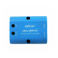
The eBox-WIFI module serves as an RS485 to WiFi converter, enabling communication between a controller and a monitoring device (such as a smartphone via an APP). Its primary function is to facilitate wireless monitoring of the controller's status and data. The device is designed to operate in AP mode for APP-based monitoring. Attempts to switch it to AP+STA mode for PC-based monitoring have been identified as the cause of the module becoming "dead" or unresponsive. The restoration method described herein aims to revert the module to its original, functional state.
Important Technical Specifications
While specific technical specifications like voltage, current, or data rates are not explicitly detailed in the provided text, the document implies several key aspects:
- Connectivity: RS485 to WiFi conversion.
- Operating Modes: Primarily designed for AP mode (Access Point) for APP connectivity. AP+STA mode (Access Point + Station) is mentioned as an unsupported configuration that leads to device malfunction.
- Components: The device includes a WiFi chip, a reset button (S1), and various capacitors (C7, C8, C9, C10, C11) and resistors (R2, R5). It also features LED indicators for "Power" and "Link."
- Power Supply: The WiFi module receives power from the controller it is connected to.
- Physical Interface: Includes an RJ45 port for RS485 connection.
- Firmware: The issue arises from an unsupported firmware configuration change, suggesting the device relies on specific firmware for its operation. The restoration process effectively reloads or resets this firmware.
Usage Features
The eBox-WIFI module is designed for straightforward use with a dedicated mobile application for monitoring controllers.
- APP-based Monitoring: The primary intended use is to monitor the controller via a mobile application when the eBox is in AP mode.
- Ease of Connection: It acts as a bridge, simplifying the process of connecting an RS485-enabled controller to a wireless network.
- Restoration Process: The document details a specific, multi-step procedure for restoring the module if it becomes unresponsive due to unauthorized mode changes. This process involves:
- Disassembly: Opening the eBox shell to access internal components.
- Identification of Components: Locating the fourth pin of the WiFi chip and the right pin of capacitor C7.
- Powering On: Ensuring the controller and WiFi module are powered.
- Short Circuiting (Step 3): Briefly short-circuiting the fourth pin of the WiFi chip and the right pin of C7 using tweezers. This action is crucial for initiating the restoration sequence.
- Reset Button Activation (Step 4): Immediately after releasing the short circuit, pressing and holding the reset button (S1) for 5 seconds or more. This step likely triggers a reset or firmware recovery mode.
- Second Short Circuit (Step 5): Releasing the reset button and immediately performing another short circuit between the fourth pin of the WiFi chip and the right pin of C7. This second short circuit, combined with the previous steps, is intended to complete the restoration.
- Verification: The successful restoration is indicated by a single flash of the "Link" light.
- Future PC Monitoring Support: The manufacturer acknowledges the demand for PC-based monitoring and plans to release a video guide and potentially an updated solution to support this functionality in the future.
Maintenance Features
The document primarily focuses on a specific restoration procedure rather than general maintenance. However, the outlined steps can be considered a form of advanced user-level maintenance for troubleshooting and recovering the device from a specific software-related failure.
- Self-Recovery Mechanism: The detailed restoration method empowers users to recover their device without needing to send it back for service, provided they follow the instructions carefully.
- Diagnostic Indicator: The "Link" light flashing once serves as a clear visual indicator of successful restoration, allowing users to confirm the repair.
- Manufacturer Support: The manufacturer provides clear instructions and acknowledges user issues, indicating a commitment to supporting their product, even for issues arising from unsupported modifications. They also plan to release further support materials (videos for PC monitoring and restoration) to assist users.
- Warning Against Unauthorized Modifications: The document implicitly serves as a maintenance guideline by warning users against changing the internal mode of the eBox from AP to AP+STA, as this is a known cause of device malfunction. This highlights the importance of adhering to supported configurations to avoid issues.
- Required Tools: The restoration process requires basic tools like tweezers for short-circuiting, implying a level of user technical competence.
In summary, the eBox-WIFI module is a wireless converter designed for simple APP-based controller monitoring. While robust for its intended use, it has a known vulnerability when users attempt unsupported mode changes. The provided restoration method offers a detailed, step-by-step guide for users to recover their device, emphasizing the manufacturer's commitment to user support and future enhancements for broader monitoring capabilities.