M200 / M205 / M100 / M105 Series Revision A
Disassembly/Reassembly Routing FFCs/cables 57
Confidential
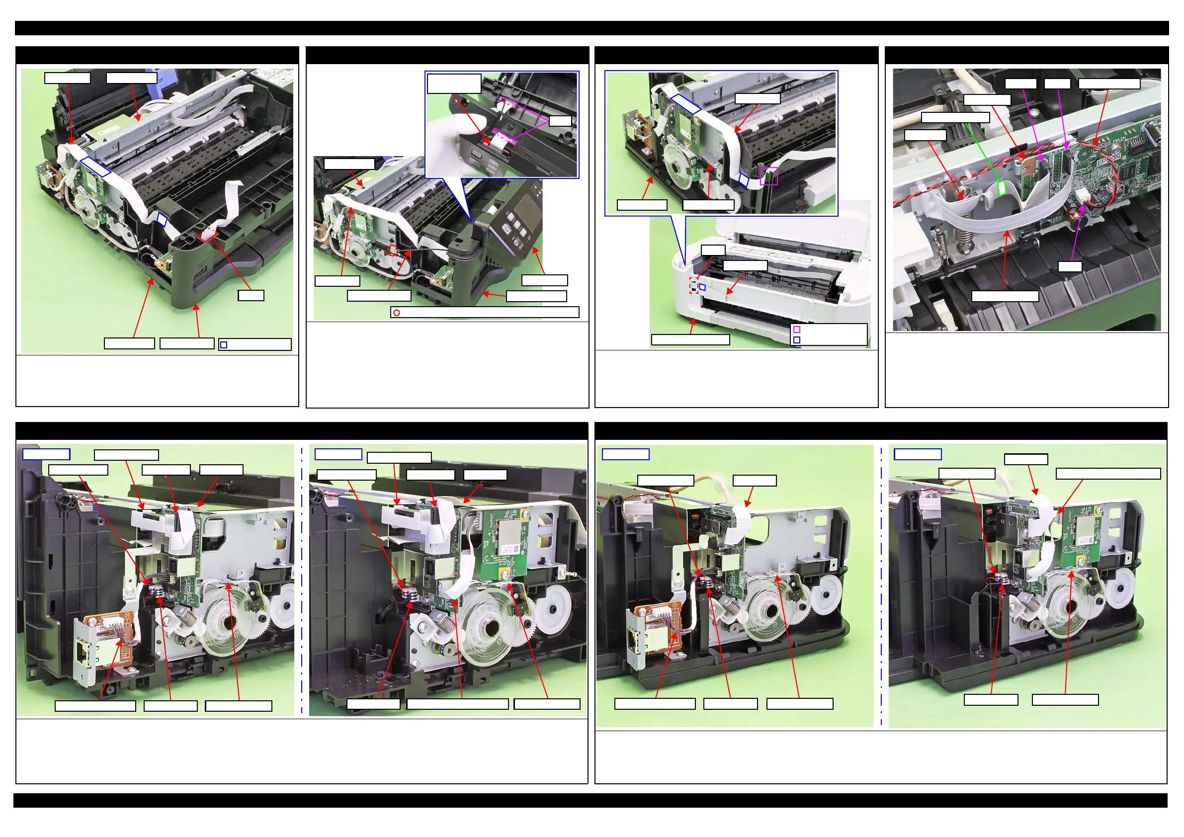
Panel FFC (M200/M205 Series)
Route the Frame Base and Main Frame along the folded line and secure
with the double-sided tape on the position shown in the above.
After installing the Housing Front, route the Panel FFC through the hole
of the Housing Front.
Housing Front
Main FramePanel FFC
Frame Base
Hole
Double-sided tape
Panel Unit (M200/M205 Series)
Route the Panel FFC and grounding wire as follows before installing the
Panel Unit.
• Route the Panel FFC through the hole of the Panel Unit and connect the
connector of the Panel Board.
• Route the grounding wire through the hole of the Housing Front.
After installing the Panel Unit, secure the grounding wire to the Main
Frame on the position indicated in the figure above with screw (x1).
Hole
Connector of
Panel Board
Main Frame
Panel FFC
Grounding wire
Housing Front
Panel Unit
C.B.S-TITE SCREW 3x6 F/ZN-3C (6 ± 1 kgf·cm)
Panel FFC (M100/M105 Series)
Route the Panel FFC through the rib of the Frame Base and Main Frame
along the folded line and secure with the double-sided tape on the position
shown above.
Route through the hole of the Housing Upper Assy and secure with the
double-sided tape on the position shown above.
Rib
Double-sided tape
Panel FFC
Frame Base Main Frame
Housing Upper Assy
Panel FFC
Hole
Right side of Main Board
Connect the following cables/FFCs to the Main Board as shown in the figure
above.
• CR Motor cable (CN12)
• CR Encoder FFC (CN6)
• Head FFC (CN102)
Secure with the double-sided tape on the position shown above.
Main Board
CN12
CN102
Head FFC
CR Encoder FFC
CN61 CR Motor cable
Double-sided tape
Left side of Main Board (M200/M205 Series)
Connect the following cables/FFCs to the Main Board as shown above.
• PF Motor cable (CN13) • PS Unit cable (CN501)
• Wireless LAN Module Cable (CN4: only for M205 Series) • PF Encoder FFC (CN7)
• Ethernet Board cable (CN14: only for M200 Series)
• Panel FFC (CN2) : Secure the ferrite core of the FFC Holder MB and connect to the Main Board through the ferrite core.
M205 Series
PS Unit cable PF Encoder FFCWireless LAN Module Cable
FFC Holder MB
Ferrite core
Panel FFCPF Motor cable
M200 Series
PF Motor cable
PS Unit cable PF Encoder FFC
FFC Holder MB
Ferrite core
Panel FFC
Ethernet Board cable
Left side of Main Board (M100/M105 Series)
Connect the following cables/FFCs to the Main Board as shown above.
• PF Motor cable (CN13) • PS Unit cable (CN501)
• Wireless LAN Module Cable (CN4: only for M105 Series) • PF Encoder FFC (CN7)
• Ethernet Board cable (CN14: only for M100 Series) • Panel FFC (CN2)
M100 Series
Ethernet Board cable PS Unit cable PF Encoder FFC
PF Motor cable Panel FFC
M105 Series
PS Unit cable PF Encoder FFC
PF Motor cable
Panel FFC
Wireless LAN Module Cable
 Loading...