M200 / M205 / M100 / M105 Series Revision A
Confidential
Disassembly/Reassembly Disassembly/Reassembly Procedures 45
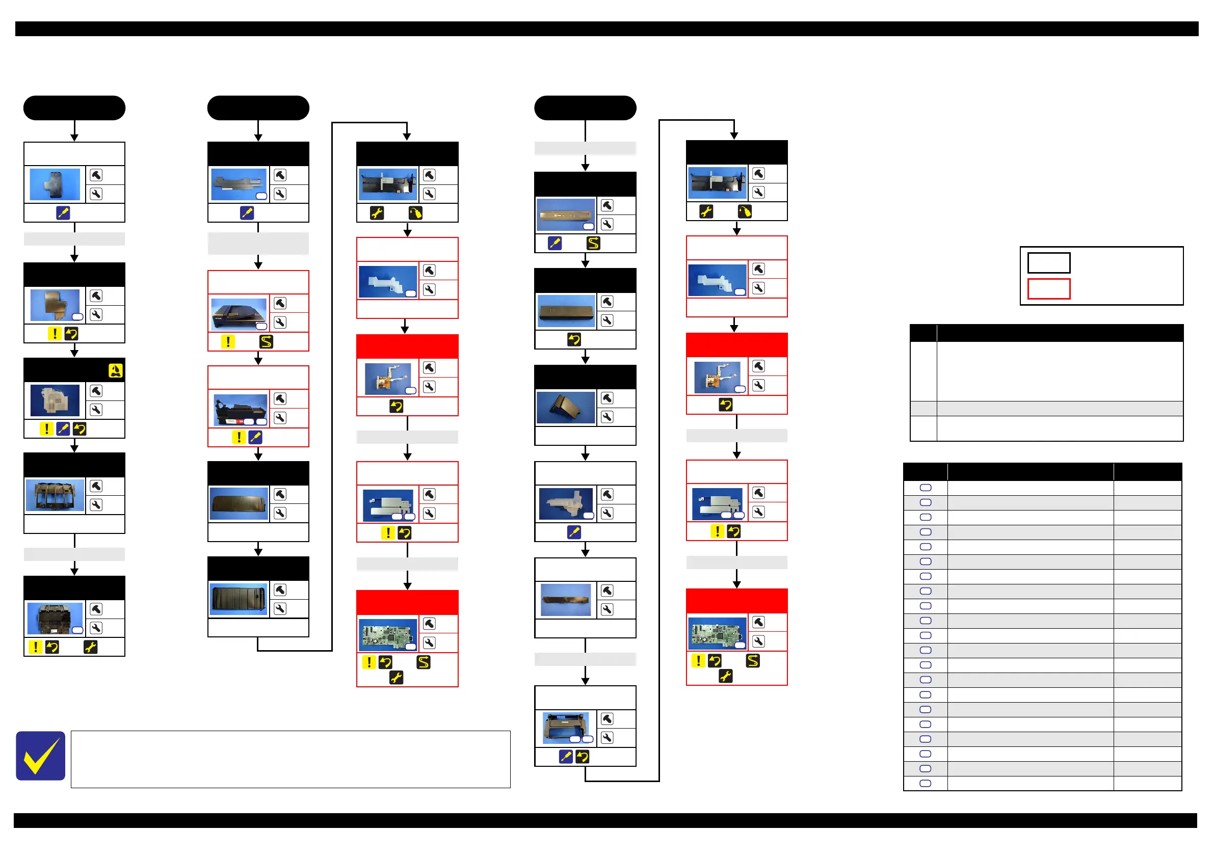
2.2.3 Disassembly Flowchart (Printhead/Main Board)
Flowchart 2-4. Disassembly Flowchart (Printhead/Main Board)
Printhead
START
FFC Cover
Outer
---
1
(p 50)
CR Encoder FFC
Holder Board
---
2
---
Printhead
3
---
(p 49) (p 59)
S10
START
Scanner FFC
Grounding wire (x2)
Housing Rear
1
4
(p 47)
S6
ADF/
Scanner Unit
1
2
(p 46) (p 56)
S6
Paper Support
---
4
---
Hopper
---
2
(p 59) (p 73)
FFC/Cable* 10
Main Board FFC
Holder
1
2
---
S15
Paper Support
Sub
---
5
---
FFC/Cable* 11
Shield Plate
3
---
(p 52)
S14 S17
Main Board
1
---
(p 52) (p 57)
(p 59)
S15
The Printhead can be replaced without removing the ADF/Scanner Unit. However, the
working space for replacement is narrow and dark. Therefore, if you find it difficult to
work, remove the ADF/Scanner Unit first before replacement.
FFC/cable list
No. FFC/Cable
10
Remove/disconnect the following.
HeadFFC (CN102)
CSIC FFC (CN6)
PF Motor cable (CN13)
PS Unit cable(CN501)
11 Remove/disconnect all FFCs/ cables.
12
Remove the double-sided tape of the Panel FFC (CN2) and remove the
FFC/Cable from the Housing Upper Assy hole.
Ethernet Board
Assy
1
2
(p 50)
S7
Main Board (Multifunction Printer)
START
Main Board (Singlefunction Printer)
Panel FFC
Panel Unit
2
6
(p 48) (p 57)
S7
Housing Upper
Assy
5
13
(p 47)
S6
S21
FFC/Cable* 12
Housing Left
Assy
5
6
(p 47)
S6
S16
Adapter Cover
1
4
(p 49)
S9
Adapter
---
1
(p 54)
Head FFC
Ink Supply Tube
Guide 1st
1
3
(p 52)
S7
Ink Supply Tank
Cover
---
---
(p 54)
Ink Tube Cover
---
---
---
Frame Base
Support
---
---
---
Hopper
---
2
(p 59) (p 73)
FFC/Cable* 10
Main Board FFC
Holder
1
2
---
S15
FFC/Cable* 11
Shield Plate
3
---
(p 52)
S14 S17
Main Board
1
---
(p 52) (p 57)
(p 59)
S15
Ethernet Board
Assy
1
2
(p 50)
S7
Model-specific parts/unit
Common parts/unit
Screw type/torque list
Symbol Screw Type Torque
C.B.P-TITE (S-P1) SCREW 3x12 F/ZN-3C 6 ± 1 kgf·cm
C.B.P-TITE SCREW 2.6x5 F/ZN-3C 6 ± 1 kgf·cm
C.B.P-TITE SCREW 2x8 F/ZN-3C 2
± 0.5 kgf·cm
C.B.P-TITE SCREW 2x8 F/ZN-3C 2.5 kgf·cm
C.B.P-TITE SCREW 2x8 F/ZN-3C 4
± 1 kgf·cm
C.B.P-TITE SCREW 3x10 F/ZB-3C 6 ± 1 kgf·cm
C.B.P-TITE SCREW 3x10 F/ZN-3C 6
± 1 kgf·cm
C.B.P-TITE SCREW 3x10 F/ZN-3C 5 ± 1 kgf·cm
C.B.P-TITE SCREW 2.5x8 F/ZN-3C 2.5
± 0.5 kgf·cm
C.B.P-TITE SCREW 3x10 F/ZN-3C 7 ± 1 kgf·cm
C.B.P-TITE SCREW 3x8 F/ZN-3C 6
± 1 kgf·cm
C.B.P-TITE SCREW 3x6 F/ZN-3C 6 ± 1 kgf·cm
C.B.S-TITE (P2) SCREW 3x6 F/ZN-3C 7
± 1 kgf·cm
C.B.S-TITE SCREW 2x4 F/ZN-3C 2 ± 0.5 kgf·cm
C.B.S-TITE SCREW 3x8 F/ZN-3C 6
± 1 kgf·cm
C.B.S-TITE SCREW 3x6 F/ZB-3C 6 ± 1 kgf·cm
C.B.S-TITE SCREW 3x6 F/ZN-3C 6
± 1 kgf·cm
C.B.S-TITE SCREW 3x6 F/ZN-3C 8 ± 1 kgf·cm
C.B.S-TITE SCREW 3x6 F/ZN-3C 7
± 1 kgf·cm
C.P-TITE SCREW 3x4 F/ZN-3C 4 ± 1 kgf·cm
C.B.S-TITE SCREW 3x8 F/ZB-3C 6
± 1 kgf·cm
S1
S2
S3
S4
S5
S6
S7
S8
S9
S10
S11
S12
S13
S14
S15
S16
S17
S18
S19
S20
S21
 Loading...