EasyManua.ls Logo

ERARD STANDiT 400 User Manual

ERARD STANDiT 400
6 pages
To Next Page IconTo Next Page
Page #1 background imageLoading...
Page #1 background image
I
Ø6
Ø8
a1
A
C
E
F
G H
J
x6
B
x2
x2
x3
K L M
N
D
WWW.ERARD.COM
STANDiT 400 notice USA MGS170324
40.4" ... 48.2"
VESA
400
300
200
BREVET & MODÈLE DÉPOSÉS - PATENTED DESIGN
NO DRILL WALL MOUNT FOR FLAT SCREEN TV
SOPORTE MURAL PARA PANTALLA PLANA SIN TALADRO
SUPPORT MURAL SANS PERÇAGE POUR ÉCRAN PLAT
66 lb
*
FOR SCREENS MAX 2 INCHES DEEP
ÉPAISSEUR ÉCRAN MAXI 2 POUCES
2"
maxi
*
REF : 044662
2.75"
2.35"
2.00"
44 lb 55 lb 66 lb
TOO HEAVY vs
THICKNESS !
(black area)
WEIGHT OK vs
THICKNESS
(white area)
SCREEN THICKNESS
WEIGHT
66 LB AND 2" ARE THE MOST COMFORTABLE
LIMITS AND MEANS THAT THE SCREENS ARE
LIMITED TO 2" THICK AND 66 LB. IN REALITY YOU
CAN FINE TUNE THE PARAMETERS AS FOLLOWS :
*
1.2
"
Question and Answer IconNeed help?

Do you have a question about the ERARD STANDiT 400 and is the answer not in the manual?

ERARD STANDiT 400 Specifications

General IconGeneral
Mounting typeFloor
Maximum VESA mount400 x 400 mm
Minimum VESA mount200 x 200 mm
Maximum screen size52 \
Minimum screen size30 \
Maximum weight capacity30 kg
Panel mounting interface200 x 200, 300 x 300, 400 x 400 mm
TypePortable floor stand
Weight and Dimensions IconWeight and Dimensions
Weight- g
Thickness50 mm

Summary

Product Specifications and Components

VESA Compatibility

Details VESA mounting hole patterns supported by the stand.

Weight and Screen Size Capacity

Specifies the maximum weight (66 lb) and screen size (30-55") the stand can support.

Screen Thickness Guidelines

Illustrates acceptable screen thickness ranges for optimal weight distribution.

Parts Identification

Lists and labels all included hardware and stand components for assembly.

Assembly Instructions

Step 1-3: Assembling Base Structure

Connects base components using specific screws and parts.

Step 4-5: Attaching Vertical Support

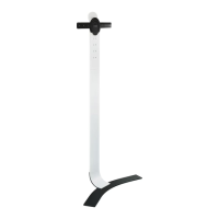
Secures the main vertical support to the assembled base.

Step 6-7: Preparing for TV Mounting

Selects appropriate hardware and attaches mounting brackets to the TV.

Step 8: Mounting to Stand

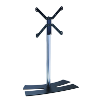
Attaches the TV with brackets to the main stand structure.

Step 9-10: Positioning and Cable Management

Guides the stand to its final position and organizes cables.

Step 11-12: Securing TV and Height Adjustment

Locks the TV onto the stand and adjusts its height.

Step 13-14: Final Checks and Customization

Ensures secure attachment, offers customization options like painting.

Customer Support and Customization

Customization Options

Information on personalizing the stand's appearance with paint.

Contact Information

Provides customer service phone numbers and email address for support.

Related product manuals