EN
32
09
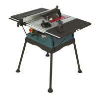
Foldable stand (Fig. P, Q, R, S, T, U)
Support frame (Fig. P)
1. Loosen the hex nuts M5 with 8 mm open-end wrench (not supplied) and remove
them with screws (M5 x 35 mm), flat washers 5 on the foldable stand (11).
2. Insert the support frame (13) into the foldable stand (11). Align the holes on support
frame (13) to the holes on foldable stand (11).
3. Fit the screws (M5 x 35 mm) with flat washers 5 through the holes and secure them
with hex nuts M5 and flat washers 5.
Transport handle (Fig. Q)
1. Insert the transport handle (17) into the holes of foldable stand (11).
2. Fit the screws (M6 x 25 mm) through the holes of transport handle (17) and secure
them with nuts M6.
Unfold stand (Fig. R, S)
1. Loosen the locking knob (10) (Fig. R step 1), step on the support frame (13) (Fig. R
step 2), pull the locking lever (18) out to unlock it (Fig. R step 3) and lift the transport
handle (17) (Fig. R step 4) to highest position to unfold the stand. Release the
the locking lever (18) and transport handle (Fig. R step 5) afterwards.
2. Make sure the locking lever (18) and locking knob (10) snap into correct position
(Fig. S). Tighten the locking knob (10).
Balance bar (Fig. T)
1. Rotate the support bolt (66) clockwise to its highest position. Slide the two hex bolts
(67) into the slot of the balance bar and attach two support blocks (68). Make sure
the flat side is toward the balance bar.
2. Align the two hex bolts to the two holes of the support frame (13) bar and secure
them with two locking knobs (69).
Transport wheel assembly (Fig. U)
1. Loosen and remove the wingnuts (70), support feet (29) and the hex locking nuts
(71) and the flat washers (72) as well from the transport wheel assemblies.
2. Insert the bolts (76) with clamping plates (73), brake (74) and brake pedals
(75) into the hole of transport wheel (12). Make sure the four locating plates of the
clamping plate (73) snap into the four slots of the transport wheel (12). The side
shape of brake pedal (75) must match the brake.
3. Insert bolts (76) through the hole of leg. Ensure the bolt (76) is engaged into the
square hole properly. To ensure the correct function of the brake, the indicator
marking “A”/ “B” on the brake should comply with the one on the leg.